Monday, 5 December 2016

Nook Simple Touch

Resurrecting an old Nook Touch

In a quest to find some larger e-ink screens for projects I came across the Nook Simple Touch, which features a 600x800 e-ink touch screen.
I picked one up from eBay to potentially steal the screen, or at least hack an interface for a Raspberry Pi or Arduino.
As it happens, the 800MHz processor package isn't too bad to power your own projects. The wireless can hook up the screen to a network and provide an interface most projects without opening the back.

Getting the Nook working

If you are in the UK then B&N have stopped supporting the Nook devices on their book store. This also means you cannot register a device. The first hurdle to overcome is the registration to use the device. It's also a prerequisite to rooting. 

If you ask B&N nicely they will give you the following steps:
1. Turn on and wait for the welcome screen
2. Press the top right page turn button and at the same time swipe across the top of the screen (left to right)
3. The Factory button will appear. Press this to activate the factory settings screen
4. Hold down the same button as before (top right page button) and at the same time tap the bottom right of the screen.
5. A Skip Oobe button will appear as shown in the image below. Press this button.


You can now use the Nook Simple Touch without registration.

As it is the Nook can connect to a PC and PDFs or e-books can be uploaded to the device memory for reading on the screen.

Rooting

Rooting the device allows additional Android applications to be loaded, but don't expect to be loading up the latest apps from the store. The device only supports Android 2.1 and any potential hacks to upgrade will only get as far as Gingerbread.

Nook Manager is one of the many rooting apps available and I found it easy to use. It also allows an SSH server and/or a remote ADB to be run on the device.

I did have success installing the play store and logging in to my account. It does take some time to activate properly. The result were apps, which either crashed or were so old the services they used were no longer available. The BBC News app was the only one I could get working.

On the plus side the Nook Manager app is fairly easy to reverse engineer and is actually a good example to get started on custom code for the Nook Touch. Under the hood there's an Android Linux OS which will run code compiled for the ARM 7 processor so with a bit of cross compilation the device can be made to dance to your tune.

Custom code

Following the Nook Touch example and writing to the frame buffer directly allows 16 bit grey scale images to be displayed. For custom use none of the Android environment is needed. 
The great thing about the Nook is that it boots from the external SD card slot so custom kernels and ramdisk images can be loaded up without overwriting the old Nook system stored in internal memory. 

Managing the uRamdisk images requires a Linux system with dd and mkimage tools or a Window's tool can be downloaded called ImgUtil

Customise the init.rc start up script to run anything you want at start-up. Nook Manager runs a system_ready script when booted.

Example code on the Nook

A little application I've written provides weather reports from Open Weather Map on the Nook screen. 
This writes to the frame buffer directly, reads ZForce inputs from the touch screen and reads inputs from the buttons around the screen.
All code can be found in GitHub at https://github.com/AidanHolmes/NookDisplay. This also uses the graphics library at https://github.com/AidanHolmes/graphicslib

It's cold but maybe not that cold openweathermap

Sunday, 16 October 2016

Revisiting Sparkfun Colour LCD

Python for Sparkfun Colour LCD

Some time ago I posted code and setup notes to get the Nokia6100 screens, featuring on the Sparkfun Arduino shield, working on a RaspberryPi.
The examples were written in C/C++. This isn't so useful when the majority of users are working with Python so I decided to revisit and provide a useful object class to handle the display.

Setup

The shield is configured to fit straight on top of the Arduino. This doesn't mean it cannot work on other platforms. A bit of creative use of jump leads can get this working quite as effortlessly on the Pi.
The obvious connections are to 3.3V, 5V and GND. 
The other pins go to SPI (ensure it's enabled on your Pi in raspi-config).

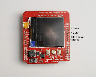
From the shield connect:
Pin 13 (Clock) to 11 (SCLK) on a Pi
Pin 11 (MOSI) to 9 (MOSI) on a Pi
Pin 9 (CS) to 8 (CS0) on a Pi
Pin 8 (Reset) to any free GPIO of your choice. I used 25

The 3 buttons are connected to 3, 4 and 5 on the shield. I'm not going to cover the buttons here as it's another topic. RPi.GPIO library provides everything you need to get them working.

Software for the Raspberry Pi

Python code for the Pi can be found on my GitHub site at https://github.com/AidanHolmes/Nokia6100.

The code hasn't been made into a module or anything fancy.

from nokia import Nokia6100
should be enough to create the connection and send PIL images to the 132x132 LCD display.

This works on the shields with the Philips PCF8833 display as this is the variant I have. Code for the Epson display is included, but not tested. Start up sequence and code for the Epson is mostly borrowed from Jame P. Lynch's code on the Sparkfun site in Nokia LCD Display Driver.pdf.

Quick Start

from nokia import Nokia6100
from PIL import Image

disp = Nokia6100(25) # Assuming SPI bus 0 and CS0 used
disp.initialise()

img = Image.open('myimg.jpg')
disp.display(img)

Reference

The interface for the Nokia6100 class can be found on the GitHub page. It's quite a small set of functions. PIL does all the hard work with images so the functionality is just about the hardware control. 

Performance

The C/C++ code pushes data over SPI faster than the Python. It's fairly marginal and both the Python and C/C++ code can be seen to redraw the display. The redraw is more apparent using Python whilst the C/C++ code is a quick flicker. 
I'm not quite sure what the real speed is over the Raspberry Pi's SPI, but I expect that the real speed isn't the max speed set in spidev.

In any case, I wouldn't expect the LCD to handle rapidly changing displays very well with user-space code driving the display.

Tuesday, 30 August 2016

pHat Stacking

Hat Stacking Pimoroni pHats

Pimoroni sell the Enviro pHAT, which is a really good little package to go on top of a Raspberry Pi. 

I was looking around for a temperature and humidity sensor and this has all of that plus motion, colour and analogue. I'm not sure how all of these can be used together but even separately these components can cost you more in separate breakout boards so not much loss to only use 1 or 2 of these features.

Combined with Scroll pHAT


The Scroll pHAT is great for text. Combined with the Enviro pHat this can show temperature, heading, pressure and motion.

The video shows the motion sensors reaction to being moved in the x and y axis. The dot can be thrown around which is a fun bit of code. 

Combined with Unicorn pHat


The Unicorn pHAT is just a colour frenzy. Text can be displayed, but this is fairly limited due to only having 4 LEDs high to play with.  
To show the light/colour sensor I sent the values directly to the Unicorn pHat.

Blue

Green

Red

Yellow
The camera doesn't pick the colours up as clearly as they were shown. The colours weren't correct for green and this showed up as a blue colour, but quite fun to play around with.


Saturday, 13 August 2016

PaPiRus GPS

Low Power GPS Tracker


PaPiRus e-ink screen is an interesting display for the Raspberry Pi. I thought it would be a good idea to start putting the screen to work and try out something I could take out and use. 

GPS has saved me when footpaths disappear in the middle of nowhere. A dedicated device to help locate me and also track where I've been seemed like a good project idea. This current instance is fairly basic but the plan is to steal a few ideas from fitness and tracking apps and reuse here.

Specification

Portable, low power, battery supplied, GPS device with the ability to view where I am on the OSGB36 grid and run for at least 3 hours.
In detail:
  • 3 hours running time
  • Log my journey and provide a view of the data
  • Start/stop the logging
  • Provide
    • Distance
    • Split time per mile 
    • Where I am on the OSGB36 grid and WGS84
Secondary goals
  • Min/max altitude
  • Climb rates split per mile
  • Visible mapping of journey

What's gone into the build?

A PaPiRus screen has been included to provide a low power display solution. The build uses the full sized PaPiRus and it works fine attached to a Pi Zero. 
The Pi Zero was used because, it's cheap, small and should also help keep the power usage low. The Zero's ability to work as a gadget over USB is awesome for a device in a box. Network gadget feature is used so the software can be maintained easily and web services provided. 
The cheaper GP-20U7 module has been selected from Proto-Pic for use in this build. The JST connector was cut off and a jumper connector added to work with a custom strip board.
A Sparkfun LiPo charger and power booster has been included to provide power using either 400, 500 or 1000mAh LiPos. The aim is to use the 1000mAh to get the longest life. An evolution of the design included power management and this is handled by a Sparkfun Fuel Gauge.

The luxury items here are the push buttons. These are from Sparkfun and come with illuminated LED rings. 
A custom strip board has been used to add in headers to connect up buttons, I2C and the GPS. A couple of NPN transistors are on the board to switch 5v to illuminate the button LEDs. 
To provide some connectivity to the outside world a female USB breakout board from Sparkfun has also been used with a stripped down micro USB cable to provide power and data.

All of these components are housed in a 41x77x101 ABS. It's a fairly snug fit for the PaPiRus, Zero and strip board. 

After some drilling and cutting, all the components fit in neatly. Liberal use of electrical tape provides some protection from components touching and sending 5/3.3v the wrong way.

Getting it running

By default the PaPiRus display uses the UART pins, but there's a build option for the PaPiRus to exclude these and change the required GPIO pins used by the display. UART pins are used by the GPS module so excluding them was necessary. This was tested before assembly of the components by carefully running jumper pins to the PaPiRus. Unfortunately there was one issue which only revealed itself on assembly which was down to the RXD line. When GPS data is actually going to the RXD the PaPiRus display wouldn't work. 
Header surgery on the Pi Zero

The only option at this stage was to snip the GPIO pin going to the display. In hindsight this could have managed this on the strip board layer by designing it to sit between the Zero and the PaPiRus. I wouldn't have been happy to do this to my Pi 2 or 3, but this isn't a concern with the Zero as there are no plans to reuse it on another project.

Controls

The 2 buttons provide basic control. The green button provides a way to change the display and when held it will shutdown the Pi Zero. The white button provides a way to enable the GPS tracking by holding the button and also control what's displayed on the screen with a brief press. 
A top switch was fitted later into the build as a way to pull the EN line low on the LiPo booster and charger to reduce the power consumption. This doesn't entirely stop the battery from draining due to a quiescent current and a pull up resistor on the EN line. The switch also disconnects the LiPo Fuel Gauge to prevent any charge being lost through the MAX17043

View of final assembly


Video

This is a basic demonstration to show the GPS and how the e-ink screen looks presenting the data

Thoughts

My initial wiring of the strip board included a connection to the SCL pin to wake from halt. Whilst this worked to wake up the Raspberry Pi this wasn't a very logical mix with another GPIO input pin and caused false pin state changes and interrupted the SCL when pressed. The connection was removed after implementing the power switch and provided another way to start up after halting.

A micro USB wire was stripped adding female jumper connectors to break out the power and data lines. Since this was a 4 wire USB cable it didn't come with an ID line. A 5 wire cable would allow this to be connected and an OTG connection supported. OTG would allow a WiFi dongle and connection to a hub to support more devices and charging. 4 wire is fine and the network gadget functionality provides charge and connectivity.

The ability to completely turn off power would be useful. Putting the switch in-between the LiPo and charger would allow complete isolation and prevent slow battery drain. The 1000mAh battery seems to drop by 8% a day at the moment, but this hasn't been measured properly. 

Monday, 1 August 2016

Sparkfun Lipo Fuel Gauge

Power Cell and Fuel Cell Integration

As part of a larger project I've used the Sparkfun Power Cell and the Sparkfun Fuel Gauge boards to provide power, charging and reporting for a LiPo battery. 
This post is about how the components can be configured with a Raspberry Pi and code which can be used to read the Fuel Gauge.

Power Cell

This board is a great size for a project due to the square setup of the components. There's a couple of small changes, which would be good to see and that's having all the pins on one side and also including access to the battery terminals. I had to solder a couple of pins to the underside of the Power Cell to access the battery terminals for the Fuel Gauge. For my current project I don't use the micro USB and instead I wire into the charge pins. This widens the board footprint when using jumper headers.

Adafruit also sell the similar PowerBoost 500 board and this retails at a slightly lower price. I have one of these for another project and it appears to facilitate pins on just one side so it may be a future favorite.


Fuel Gauge

This small board fills an essential gap for any project using a battery. We are all so used to consumer technology telling us how much power we have remaining that, unless you are OK with a project just shutting down without warning, then this is going to be an important feature. I like that this is quite a small and easy to embed into a small gap.
Sparkfun sell an all-in-one board called the Babysitter and although this has all the components in one board it's quite big. I haven't yet seen the Babysitter for sale in the UK so for that reason I also settled for the Fuel Gauge.
For my use the JST connector was a bit useless and it would be nice to have just a breakout board for the MAX17043. Architecturally it's feasible to connect a battery to this board first and wire up jumpers connected to another female JST to go into the charging board. I've not tried it this way and can't guarantee that this would work, but could be tidier in some solutions.
Be aware that the VCC and GND pins provide output. I mistakenly thought these were to power the logic but that comes direct from the battery. Luckily I got away with this and didn't fry my Pi although I was surprised to see my Zero attempting to boot up when powered from the 3V rail.


Wiring Up

I've tried to show this in Fritzing as I don't have a neat breadboard setup to provide a visual. In my setup I have an independent female micro USB for power and data. The Pi Zero can be powered from the data USB which I take advantage of. The micro USB connection shown here is actually a 4 wire, male USB cable with female jumper cable connectors. 5 wire is necessary to have OTG functionality over USB.
If you just want to power your Pi then you can remove the USB connectors and plug straight into the Power Cell. The 5V and GND outputs can go directly to the GPIO pins 4 & 6. 
A switch has been included to pull the EN pin low to stop power going to the Pi Zero. I also use it to cut the ground pin to the Fuel Gauge. 
The Fuel Gauge is shown as a MAX1704X board since there isn't a part in Fritzing. SDA and SCL are connected up to allow I2C communication. GND needs to go to a GND on the Pi to allow the logic to work on the Fuel Gauge. I haven't used the alerting output in my project as I'm not sure when I would need a hardware interrupt instead of my own software control. 
Finally you can include any LiPo battery as long as it meets the specification of the Sparkfun Power Cell and Fuel Gauge. I've shown a 110mAh as it was a small example for this diagram, but practically that will be too small for most projects that need a few hours of operation.
I've added a picture of the (messy) implementation. I have a Sparkfun female USB breakout glued to the edge of the box. The Zero is hidden under the PaPiRus display. A power switch has been glued in to the box and pulls the EN low as shown in the diagram above. 
Note that even though the output can be switched off the Power Cell still draws a small amount of current from the battery. If left for a few days then most small batteries will completely drain. I've not confirmed how long this really takes but a few % of power has been noted to drop from a 1000mAh battery when left off overnight. 


Code for Fuel Cell

I've included a really simple example used to query the bus and read the percentage remaining and voltage. Verify the Fuel Gauge address on the bus with i2cdetect. I've found that it runs on 0x36 (0x6C MSB) and as far as I'm aware this isn't configurable. 

import smbus
import time

BATT_SENSOR_ADDRESS = 0x36

def get_batt_voltage(bus):
 high_val = 0
 low_val = 0
  high_val = bus.read_byte_data(BATT_SENSOR_ADDRESS,0x02)
  low_val = bus.read_byte_data(BATT_SENSOR_ADDRESS,0x03)
 raw_val = ((low_val | (high_val << 8)) >> 4)
 return raw_val * 1.25

bus = smbus.SMBus(1)

while True: 
 battery_remaining = bus.read_byte_data(BATT_SENSOR_ADDRESS,0x04)
 battery_voltage = get_batt_voltage(bus)

 print("Battery % = {0}, V = {1}mV".format(battery_remaining, battery_voltage))

 time.sleep(5)       

The percentage is very simple to read. So simple I didn't need to wrap in a function.
The voltage is a little more involved with the byte swapping. Practically I'm not sure why the voltage would be useful in an application. It may be significant if the battery is under load and could provide some early warnings in an application. Fully charged LiPo batteries read over 3.7V so don't worry if the value seems high as the output should be regulated by the Power Cell.


Other Info

You can find some information about batteries on the Sparkfun learn site at learn.sparkfun.com/tutorials/battery-technologies. There's a LiPo voltage curve which shows the high initial voltage and what can be expected over time. 

Adafruit PowerBoost 500 + Charger

As mentioned earlier Adafruit have an alternative LiPo 5V booster and charger, which is a good alternative to the Sparkfun board. This is a picture of one that I've bought for future use.
Breakout pins are all along the top so it's easier to plan connections in a small enclosure. I expect that this suffers from a similar amount of battery drain when EN is pulled low. 
There are more LED indicators on this board than the Sparkfun and these show low battery (red), 5v active (blue), charging (yellow) and fully charged (green). This is great for an open project, but you will need a transparent case to make the most of this for any enclosed project.
There's a good overview on the Adafruit site at learn.adafruit.com/adafruit-powerboost-500-plus-charger/overview.

Saturday, 25 June 2016

PaPiRus Clock and Temperature

Optional Extras with PaPiRus

Following a bit of tinkering with the PaPiRus clock and temperature chips I thought I'd post about the implementation. 

I'm not claiming originality in this post as Frank Seliger has already posted about this. You can take a look at his blogger site to get more in-depth information. 

This is part of a larger project I'm building using the PaPiRus and the internal clock and temperature sensor took my interest. I found the implementation a little more challenging and thought I would share my experiences here.

Before trying this yourself, ensure that you have I2C enabled in raspi-config.
Run
> sudo raspi-config
from the command line and enable I2C.

PaPiRus LM75B Temperature Sensor

I'm a little confused as to why this was embedded into the PaPiRus. My only thoughts were that this is used or intended to be used to control the refresh of the e-ink display and probably manage the real time clock. 
I used Frank's shell script as an example as well as referring to the LM75B spec sheet. I'm not a great computer scientist or seasoned software engineer so I find myself banging my head against a wall whenever I have to convert MSB to LSB and potentially back again. The LM75B only returns a single 2 byte word for the temperature, but I don't think I've ever had so much trouble converting it. I have to admit that I'm a real newbie to Python and feel a bit more at home in C and C++.

Code Example

Let's get down to the Python code

import smbus
import time
from papirus import Papirus
from PIL import Image
from PIL import ImageDraw
from PIL import ImageFont

SENSOR_ADDRESS = 0x48

def init_image(pap):
    # initially set all white background
    image = Image.new('1', pap.size, 1)
    return image

def write_papirus(img, text, size, x, y):
    # prepare for drawing
    draw = ImageDraw.Draw(img)

    fnt = ImageFont.truetype('/usr/share/fonts/truetype/freefont/FreeMono.ttf', size)
     draw.text( (x, y) , text, font=fnt, fill=0)

def reverse_word_bytes(w):
     bitval = int(format(w,'016b')[-8:] + format(w, '016b')[:3], 2)
    if (format(bitval, '011b')[0] == '1'):
       bitval -=2048
    return bitval

def get_temp_celsius(bus):
    raw_temp = bus.read_word_data(SENSOR_ADDRESS,0x00)
    return reverse_word_bytes(raw_temp) * 0.125

bus = smbus.SMBus(1)
pir = Papirus()

first_run = True 

while True:
    temperature = get_temp_celsius(bus)

    print(u"Temp in \N{DEGREE SIGN}C = " + str(temperature))

     img = init_image(pir)

     write_papirus(img, "Temperature", 20, 0,0)
    write_papirus(img, format(temperature, '5.1f') + u'\N{DEGREE SIGN}C', 60, 0,50)

    pir.display(img)
    if first_run:
         pir.update()
        first_run = False
    else:
         pir.partial_update()

    time.sleep(5)

Implementation Notes

Partial updates are implemented in the example above so the display may show ghosting over time.
Temperatures seem to be on the high side. I've checked against the code that Frank produced and the temperatures are the same. I can only assume that the chip is heated from the electronics on board the PaPiRus and this creates a higher reading. 

This should work with negative temperatures, but I'm not risking the entire display by putting in a low temperature condition to test this. 

I couldn't get the LM75 spec examples to correlate with the output from the PaPiRus. I'm unsure if there's an error in the examples or down to the way the SMBus code converts to LSB. I've pulled the 11 bits as specified and reversed they bytes. Python's ability to convert to a string bit representation makes this conversion obvious. 

Copy the code to a file and run with python to get output to your PaPiRus display. Note that this assumes you've installed all git code correctly. See my earlier posts for reference to gratis and PaPiRus code libraries. 

Real Time Clock

This is a fairly standard setup for the MCP7941 clock module. Jessie distributions come with the drivers so there's not much to do.

First time setup

From the command prompt
> sudo modprobe i2c-dev
> sudo modprobe i2c:mcp7941x
> sudo bash

This creates a new shell with root permission
# echo mcp7941x 0x6f > /sys/class/i2c-dev/i2c-1/device/new_device
# logout

This should setup the hwclock. Confirm this with
> sudo hwclock -r

If this is the first setup then you will see an unset hardware clock outputting the wrong time.
Assuming you have your local clock setup with NTP then the final step is simple
> sudo hwclock -w

Manual setup of the clock can be done through the date command. Check the manual to see all settings
> man date

Start-up configuration

Ensure that the following kernel modules are loaded in /etc/modules file
i2c-dev
i2c:mcp7941x

Add them to the file if they are not already there. 

A few extra lines to the /etc/rc.local file should finish the setup
echo mcp7941x 0x6f > /sys/class/i2c-dev/i2c-1/device/new_device
hwclock --hctosys

Restarting your Raspberry Pi should keep using the hwclock over NTP. This should continue to work until the PaPiRus is disconnected. Ensure you updated the /etc/modules and /etc/rc.local file if you intend to permanently remove the PaPiRus display. 

Tuesday, 31 May 2016

PaPiRus improvements

Display Refresh Improvements

Gratis changes

Since my last post about the PaPiRus display the developers of the gratis code have fixed the driver code for the display. The old code was preventing partial updates working correctly.

The display is now much improved and motivates me to use this for projects that need active information rather than the assumed static image and text. 

If you want to see this in action then go along to the https://github.com/repaper/gratis web page and look at the posted video. The counter demo now works really well and the old performance issues have been highlighted at the start of the video. 

PaPiRus changes

Code fixes have been made to fix all the issues I listed in my last post. Get the update from https://github.com/PiSupply/PaPiRus

There are some new python scripts to demonstrate access to the 4 buttons and the temperature sensor. 

Demonstration of the refresh rate improvements

I wanted to do something like this from the first time I ran code on the PaPiRus, but the updates were far too slow using the old code. 

This is a demonstration using a 10 frame animation.
I modified the ImageDemo.py in the Gratis code to open PNG files, grey scale the image and apply Floyd Steinberg dither. I removed all the resizing code and changed epd.update() to epd.partial_update() apart from the very first frame which needs an epd.update() to work correctly.
All the time.sleep(3) calls were removed and the frames update as quickly as possible. 

The effect is a stop animation of a crow flying and the trees panning along. The test intended to show a small area of change with the crow just moving and then a larger movement with the trees also moving. 

I think it does a great job with the code improvements. Ghosting and odd artifacts are to be expected as this isn't a high refresh display and graphics are better suited to other display types. 
Typically the display is good with text and static graphics, but now it's much more responsive. 

Sunday, 6 March 2016

Nokia 6100 - PFC8833 from a Raspberry Pi

Philips PCF8833 on Pi

The Nokia 6100 display has been around for many years, but I picked one up on the cheap as they are now pretty much out of stock and selling cheaper than ever before. 

I picked up a Sparkfun version whilst buying some other components and thought I'd hook it up to my Pi for inclusion in some new projects. I could tell the display was old by the tarnishing on the connectors and a bit of cleaning was needed before the soldering iron came out. 

The big issue is that you don't know if you'll get an Epson or Philips chip with the display. I believe that the Epson were included in older Sparkfun boards and Philips were later, but this is only reading between lines from various posts about the display.

Support for Raspberry Pi

There are various examples of implementations with the Pi on the Internet. Most of these are bit banged examples or some bizarre serial hack to work in 9bit mode. Most seem to report poor performance or complex arrangement of pins. 

I downloaded one example to only get garbage on the screen and this was for a Philips.
In the end I decided to roll my own and create yet another example of working code for this display. My world is C/C++ but the examples can easily be converted to Python once the implementation is understood.

The best source of information was from Jim Lynch which is linked to from Sparkfun's site at http://www.sparkfun.com/tutorial/Nokia%206100%20LCD%20Display%20Driver.pdf.
The old link for the Philips driver is now missing from Sparkfun, but I found it linked from engpedrorafel's github site. 

Writing 9 bit SPI to Raspberry Pi

The shield has been built for Arduino boards, hence the pin layout and extra pins which are not used.In addition to the physical layout the Arduino's can implement 9bit serial communications to the display. Try and do this with Linux on a Pi and it really doesn't want to work. This is due to the Linux spidev driver being limited and not supporting LoSSI protocol.

Deep down on the Broadcom 2835 it does support LoSSI but after some playing with the BCM2835 library I only got as far as my code hanging and the SDA output doing nothing. I'm sure this can be made to work but in the meantime I hit on a better way to work using SPI using most drivers. 

Writing with 8 bit SPI


Whilst looking at reasons why the Linux driver doesn't really support LoSSI there was a simple solution presented. Why not just use 9 bytes of data for transmission and use NOOP commands for empty bytes. 
Despite the overhead of writing additional bytes, the advantage is still being able to use the SPI hardware to transfer the data and avoid too much unnecessary work in software (for instance bit banging data). 
Bytes fit into the transmission as shown above. You actually only transmit 8 bytes of data and the 9th bit for D/C uses up the space for the 9th byte of data. 

Example code

I wrote some example code using the BCM library. This has a wrapper which is good to go for C/C++. In hindsight a Python example with spidev may have been better and I may still provide one. WiringPi uses spidev but doesn't expose enough options from spidev to be useful.

The code below is very simple and sets up the display and then flashes red, green and blue screen fills as fast as possible. You should barely see the red and green fills in this code.

#include <stdio.h>
#include <stdint.h>
#include "bcm2835.h"

#define NOKIA_CMD 0
#define NOKIA_DTA 1

// global buffer
static char bitbuff[9] ;
static char prevByte ;
static int nCurByte ; // 0-8 value for 9 bytes

void writeSPI(int nDC, char byte)
{
  char out = 0x00 ;
  
  if (nCurByte == 0){  // First byte to write - exception as no prior byte
    out = (byte >> (nCurByte+1));
  }else{
    out = (byte >> (nCurByte+1)) | (prevByte << (8-nCurByte)) ;
  }
  if (nDC == NOKIA_CMD){
    out &= ~(1<<(7-nCurByte)) ;
  }else{
    out |= 1 << (7-nCurByte) ;
  }
  
  bitbuff[nCurByte] = out ;
  prevByte = byte ;

  // Fix the last byte and flush to spi
  if (nCurByte >= 7){

    // Last byte fits fully into the final 9th byte of buffer
    bitbuff[8] = byte ;

    bcm2835_spi_transfern(bitbuff, 9) ;

    prevByte = 0x00 ; 
    nCurByte = 0 ; // reset counter, just flushed 9 bytes
  }else{
    // Next byte
    nCurByte++ ;
  }
}

void flushSPI(char noop)
{
  // Add rest of bytes as NOOPS. Note Epson and Philips are different
  while (nCurByte > 0){
    writeSPI(NOKIA_CMD, noop) ;
  }
}

void LCDClearScreen(uint8_t r, uint8_t g, uint8_t b)
{  
  uint8_t byteout = 0x00 ;
  long i; // loop counter
  long c; // colour counter
  char clear_rgb[] = {0x00, 0x00, 0x00} ;

  clear_rgb[0] = r;
  clear_rgb[1] = g;
  clear_rgb[2] = b;
  
  // Row address set (command 0x2B)
  writeSPI(NOKIA_CMD, 0x2B);
  writeSPI(NOKIA_DTA, 0x00);
  writeSPI(NOKIA_DTA, 131) ;

  // Column address set (command 0x2A)
  writeSPI(NOKIA_CMD, 0x2A);
  writeSPI(NOKIA_DTA, 0x00);
  writeSPI(NOKIA_DTA, 131) ;

  // write to display memory over SPI
  writeSPI(NOKIA_CMD, 0x2C); // RAMWR

  c =0;
  // 2 bytes per pixel for 12bit colours
  for (i=0;i < 131 * 131 *2;i++){
    byteout = 0x00 ;
    byteout = clear_rgb[c] << 4 ;
    c = c>=2?0:c+1 ;
    byteout |= clear_rgb[c] & 0x0F ;
    c = c>=2?0:c+1 ;

    writeSPI(NOKIA_DTA,byteout);
  }

}

void philips_init()
{
  // SLEEPOUT - turn on booster circuits
  writeSPI(NOKIA_CMD, 0x11);
  
  // turn on booster voltage
  writeSPI(NOKIA_CMD, 0x03) ;
    
  // Inversion off
  writeSPI(NOKIA_CMD, 0x20) ;
  
  // Colour pixel format 12 bits
  writeSPI(NOKIA_CMD, 0x3A) ;
  writeSPI(NOKIA_DTA, 0x03) ;
  
    // Set up memory access controller.
  writeSPI(NOKIA_CMD, 0x36) ;
  writeSPI(NOKIA_DTA, 0x10) ;
  
  // Set contrast
  writeSPI(NOKIA_CMD, 0x25) ;
  writeSPI(NOKIA_DTA, 0x30) ;
    
  bcm2835_delay(2000) ;
    
  // display on
  writeSPI(NOKIA_CMD, 0x29) ;
}    


int main()
{
  const uint8_t reset_pin = RPI_V2_GPIO_P1_22 ;  
  const char noop_cmd = 0x00 ;
  
  if (bcm2835_init() <= 0){
    fprintf(stderr, "Cannot initialise BCM library\n") ;
    return -1 ;
  }
  
  // Setup the 9 byte buffer
  nCurByte = 0 ;
  prevByte = 0x00 ;
  
  // Initialise the BCM library
  bcm2835_spi_begin() ;

  // Configure for CS0 or CS1
  bcm2835_spi_chipSelect(BCM2835_SPI_CS0) ;

  // Works with Mode 0
  bcm2835_spi_setDataMode(BCM2835_SPI_MODE0) ;

  // Nokia display sets CS on low
  bcm2835_spi_setChipSelectPolarity(BCM2835_SPI_CS0, LOW) ;

  // About 4 MHz when set to BCM2835_SPI_CLOCK_DIVIDER_64
  // Successfully driven at around 15-16MHz
  bcm2835_spi_setClockDivider(BCM2835_SPI_CLOCK_DIVIDER_64) ;

  // Reset the display using pin
  bcm2835_gpio_fsel(reset_pin, BCM2835_GPIO_FSEL_OUTP);
  bcm2835_gpio_write(reset_pin, LOW) ;
  bcm2835_delay(2000) ;
  bcm2835_gpio_write(reset_pin, HIGH) ;
  bcm2835_delay(2000) ;  

  // Only a demo for Philips PCF8833, but easy to reuse for Epson
  philips_init() ;
  flushSPI(noop_cmd) ;

  // Update as quickly as possible
  // Fill screen first with red then green then blue
  LCDClearScreen(0x0F, 0x00, 0x00) ;
  LCDClearScreen(0x00, 0x0F, 0x00) ;
  LCDClearScreen(0x00, 0x00, 0x0F) ;
  flushSPI(noop_cmd) ; // Flush any remaining bytes as NOOPs

  // Close SPI session
  bcm2835_spi_end() ;

  bcm2835_close() ;
  
  return 1 ;
}


Saturday, 20 February 2016

PaPiRus E-ink Display

Pi Gets 'Ink' Done

YotaPhone have already taken on this type of display in mobile technology and with phones only lasting about a day from full charge it's obvious why this market is looking for something new.
The low power (or no power) requirements of the display mean it only needs to change with new information.

The PaPiRus display brings this to the hands of the tinkers and future innovators.


Find the original kickstarter page at

Installation

I have a version 1.8 board which doesn't seem to be listed on the hardware version Excel sheet. I guess this quite new and from reading the message boards the documentation should be out very soon. I'm not a kickstarter backer so I'm surprised that this doesn't come with good user documentation. I hope this helps in the meantime to explain how the display works.

Get over to the git home page at
https://github.com/PiSupply/PaPiRus

This is the latest source for the Pi hat.

Prerequisites

Ensure the SPI is enabled
If you don't have it already get GIT and imaging library for Python

> sudo apt-get install git
> sudo apt-get install python-imaging

Get the fuse library if not already installed

> sudo apt-get install libfuse-dev

If you want to run some of the demos with Gratis and you don't have fonts installed then run

> sudo apt-get install fonts-freefont-ttf

Hardware

All screens connect up in the same way. Just lift the plastic connector and insert the ribbon. Push down the connector to secure in place.

The screen folds over the back of the board so ensure you have it the right way around before inserting


Getting Python code and installing

You will need to download the latest source for the PaPiRus

> git clone https://github.com/PiSupply/PaPiRus.git
> cd PaPiRus
> sudo python setup.py install    
> papirus-setup

Gratis is the beating heart of the setup. If you just want to get straight into the workings of the display then Gratis is all you really need.
https://github.com/repaper/gratis

Get the gratis driver
> git clone https://github.com/repaper/gratis.git

Note that the next lines are for the latest V321 G2 panel, but I guess this will be most new users
> cd gratis/PlatformWithOS
> make PANEL_VERSION=V231_G2 rpi-epd_fuse
> sudo make PANEL_VERSION=V231_G2 rpi-install
> sudo service epd-fuse start

The setup installs libfuse and fonts from fonts-freefont-ttf.
My first thoughts were, why do I need all this extra code baggage. If I'm using a display I usually just directly interface and I'm done.
It's not a tight kernel driver, but it works in user space world and an e-ink isn't going to complain about performance code issues.

Checking everything works

Fix broken code
> sudo nano /usr/local/lib/python2.7/dist-packages/papirus/text.py
Indent line 37 with an extra tab. Save back to original file

> sudo nano /usr/local/bin/papirus-write
Change line 39 to 
font = ImageFont.truetype('/usr/share/fonts/truetype/freefont/FreeMono.ttf', size)

Run 
> sudo papirus-config
Set screen size

The display should be good to go with the code now
> papirus-write "Test"

Should correctly write to e-ink display, if not check previous steps and SPI is enabled.

Run clock test
Fix the clock code by editing
> sudo nano /usr/local/bin/papirus-clock

Change 
from EPD import EPD
to
from papirus import Papirus as EPD

Run clock and you should see the time and date display. This refreshes every 5 seconds
> sudo papirus-clock


Included demos

PiSupply demo files

These were already run in the test above to check things are working. The install of these files puts all copies into /usr/local/bin

> papirus-write "Hello World"
> sudo papirus-clock
> sudo papirus-gol 2.7
> papirus-clear

You'll note that sudo is used on some of these examples. As far as I know this isn't really necessary as the main purpose of the epd_fuse service is to provide an interface in normal user land. Check out the gratis examples for clarity. 

Gratis python demonstration files

Python demonstration files exist in the PlatformWithOS/demo folder. These are further python scripts which can be run (ensure the epd-fuse service is running)

This is a full screen digital clock.
> python Clock27.py

Gratis C demonstration files

These files directly access the hardware and do not use the fuse service. This is actually to test the code in the service so strictly these are not examples or demos, but good to see.

The install doesn't build these by default so a further make command is needed.

Access the PlatformWithOS from within the gratis downloaded GIT repository.
> cd PlatformWithOS

For the 2.7 panel type:
> make PANEL_VERSION=V231_G2 rpi

Other older panel versions are V110_G1 and V230_G2, only use if you know you have these older panels.

Change directory to driver-common
> cd driver-common

Run the test file as root and specify the panel size.
> sudo ./epd_test 2.7

This loops through some test images which are good examples of display.
Root access is needed for this test file because it directly accesses the hardware.


Gratis driver

Fuse driver provides device files in /dev/epd directory. These can be seen when the epd service is running
> sudo /etc/init.d/epd-fuse start

The README.md file explains what the files do and if they are read or write

Example
> cat /dev/epd/version
Will give you the driver version

Whilst in the gratis driver-common directory (see example above) the epd_fuse service can also be called with the same test images without needing root. Note that it doesn't matter if you haven't built the epd_test file to do this. Actually any test XBM matching the screen dimensions can be used.

> ./xbm2bin < cat_2_7.xbm > /dev/epd/display
> echo U > /dev/epd/command

This switches to the cat image or any other image chosen in the test folder.

Sum up of the display

E-ink displays cannot be compared directly to other display types as the screen cannot rapidly change like an LCD or OLED. Images displayed are clear and sharp for text displays. Graphics require dithering because there's no grey scale which can be set.

I hope there's further improvements down the road for the driver and display. Rapid changes to the screen are possible but ghosting is a problem until a full screen refresh has been performed. 
Check out the game of life code to see ghosting examples
> sudo papirus-gol

When this has run for a few iterations there's clear ghosting on the screen. This isn't too bad and may be something that some smart folks who now have this display on their Pi can help improve. 

Driving the display is really easy with the existing software. Simple scripts can be used easily to set the screen. 

I can't really figure out what is going on with the 4 optional buttons that came with the display. I ran some simple GPIO code to see if they were just forwarded straight to the Pi pins but this doesn't seem to be the case. 
UPDATE - The buttons connect to GPIO pins 16, 26, 20 and 21. 

The real time clock and wake functions are not clear. I didn't install the pogo pin as my current case doesn't allow the connection through to the Pi board. There's no example code to show how it works so I'm hoping this appears soon.

Finally I'm not quite sure the temperature sensor feature actually works with the Pi. There's only snippets of information in the included documentation, but it seems to indicate that an ADC would be needed for the Pi and since this isn't possible out-of-the-box I can't see how it can be read. Primarily the temperature sensor is for the display to set the PWM. 

Overall it does what it should do. I'm looking forward to some cool ideas from the user community. I think a dedicated case to house the display and Pi would be great for applications.

Sunday, 7 February 2016

Sparkfun micro OLED

Sparkfun Micro OLED 64x48 Display

The 64x48 micro display from Sparkfun is a cheap and cheerful OLED display to add into a project. Adafruit also sell a  128x64 display using exactly the same SDD1306 display driver and gives you a bit more screen if you spend a few extra dollars. There's some excellent information on both sites to get you started, but both are geared towards Arduino libraries.

Micro OLED on Raspberry Pi

There are 3 ways the OLED can be hooked up using parallel, I2C and the default setup using SPI. SPI is used in the examples below.

SPI can be enabled using the raspi-config tool from the command line. If this is enabled then a /dev/spidev0.0 and /dev/spidev0.1 will be available. 

A entire post can be written on how to hookup and use SPI but this is well documented on many sites. Sparkfun has a good tutorial for SPI and I2C.

Micro OLED in action

A video to demonstrate output to the OLED display can be seen below. If a small fixed width font is used then a good number of text rows can be displayed. XBM images provide a quick format to import directly into a binary image as resources (C/C++).


SPI libraries

For Python there's an SPIDEV driver library, which is by far the easiest way to get connected up to the OLED. 
Run 
> sudo apt-get install python-spidev
to get 2.0 SPIDEV through Jessie or download the later version direct from the link above.

The SPIDEV library wraps code to talk to the kernel driver and provides a comprehensive set of functions to manage the connection. 
A simple set of attributes are exposed by the Python library to read/write settings
  • bits_per_word 
  • cshigh
  • lsbfirst
  • max_speed_hz
  • mode
Defaults should work fine but if you want you can adjust the max_speed_hz for your project. 500kHz seems to be the default speed on the Pi 2 and Pi Zero. This seems to be fast enough to run the display.

Connecting to the OLED

Example setup to connect to the OLED:

import RPi.GPIO as GPIO
import spidev
import time

spi = spidev.SpiDev()
spi.open(0,0)

GPIO.setmode(GPIO.BCM)

dc_pin    = 17 # data command pin
reset_pin = 27 # screen reset pin

GPIO.setup(dc_pin, GPIO.OUT)
GPIO.setup(reset_pin, GPIO.OUT)

This opens SPI and uses CE0 pin to address the display. Two additional GPIO pins are needed for the command type (DC) and reset pins. 17 and 27 are used in the example above, but you can use anything you like for these pins. 

Initializing the display

These steps are really important to get the display to do anything. If you read the SDD1306 spec you will see the steps are outlined as a reference, which is harder to understand how to implement for the 64x48 display. This is because the SDD1306 is actually a full 128x64 driver whereas the micro OLED is a cut down display. 

1. Pull DC high and set the reset pin low to formally reset the display. There needs to be a time period to reset the chip
GPIO.output(dc_pin, 1)
GPIO.output(reset_pin, 0)
time.sleep(0.1)

2. Enable the display, ensure command mode is set, then pull down and back up reset pin to get into a state for commands across SPI
GPIO.output(reset_pin, 1) # enable display
GPIO.output(dc_pin,0) # set to command mode
time.sleep(0.1) # wait 100ms (spec is for 5ms min)
GPIO.output(reset_pin, 0) # disable display
time.sleep(0.1) # wait 100ms (spec is for 10ms min)
GPIO.output(reset_pin, 1) # enable display

3. Display is set to initially off. Set the timing and multiplex. These are specific to the 64x48 display. 
spi.xfer([0xAE]) # display off command
spi.xfer([0xD5]) # display clock div
spi.xfer([0x80]) # set timing
spi.xfer([0xA8]) # set muliplex, 
spi.xfer([0x2F]) # note that this is specific to 64x48 displays

4. Set the display offsets. The Sparkfun is aligned to zero offsets in memory. Note this may not be the case for other implementations which use the same display driver.
spi.xfer([0xD3]) # set display offset
spi.xfer([0x0]) # com offset set to 0
spi.xfer([0x40 | 0x00]) # set startline offset to zero

5. Kick off the display
spi.xfer([0x8D]) # charge pump
spi.xfer([0x14]) # enable pump (disable with 0x00)
spi.xfer([0xA6]) # normal display
spi.xfer([0xA4]) # display all on resume

6. Next steps are for configuration. The examples here work with page addressing
spi.xfer([0x20]) # memory mode
spi.xfer([0x10]) # page address mode (10b for page, 01b for vertical)
spi.xfer([0xA0 | 0x01]) # seg remap 127 to SEG0. Rows are left to right from display ribbon
spi.xfer([0xC)]) # com scan descend. Basically flips the display from display connector ribbon
spi.xfer([0xC0]) # com scan ascend from display connector
spi.xfer([0xDA]) # set com pins
spi.xfer([0x12]) # A4 is 0 so sequential COM pin. A5 is 1 so enable com left/right remap
spi.xfer([0x81]) # set contrast
spi.xfer([0xCF]) # 00h to FFh contrast values.
spi.xfer([0xD9]) # set precharge
spi.xfer([0xF1]) # Phase 1: 1 dclk (max 15), Phase 2: 15 dclks (max 15)
spi.xfer([0xDB]) # set com deselect
spi.xfer([0x40]) # above 0.83 x Vcc for regulator output.
spi.xfer([0xAF]) # display on
time.sleep(0.1)

7. The display is now on and can be written to over SPI by setting DC high
GPIO.output(dc_pin, 1)

Drawing to the OLED

This isn't a particularly efficient method, but gives an example to show how the paged memory works and will allow you to write to the OLED memory buffer. There are 3 helper functions shown to make the code a bit more readable.

def WriteCommand(c):
        GPIO.output(dc_pin, 0)
        spi.xfer([c])
#end def

def WriteData(d):
        GPIO.output(dc_pin, 1)
        spi.xfer([d])
#end def

def SetColumnAddress(add):
        WriteCommand ((0x10 | add >> 4) + 0x02)
        WriteCommand (0x0F & add)
#end def

def DrawOLED(cx,cy):
        # 8 pixels are written on each SPI byte.
        # This is performed over 6 pages
        out = 0x00
        for y in range(0,6):
                SetColumnAddress(0)
                WriteCommand(0xB0 | y)
                for x in range(0, 64):
                        out = 0x00
                        if cx == x:
                                if cy >= y*8 and cy < (y+1)*8:
                                        out = 0x01 << (cy - (y*8))
                        WriteData(out)

Taking this into real projects

All the code shown are just examples and should be enough to expand for use in real projects. Code libraries can be built in C/C++ using the same underlying spidev calls via ioctl to the kernel driver.


My own code is a C++ library implementation making almost identical calls seen here. The main differences consist of an improved method using internal buffer in the code, which is written out to the OLED in a single full write of the display. This matches the Arduino code approach from Sparkfun. I may publish this at a later date as a useful Pi library for C++ development.