Saturday, 7 October 2017

GPS logger and Google Maps


It has been a while since I posted about the Raspberry Pi Zero, PaPiRus and GPS logger.
Since the post I've updated further with a web service for displaying routes with Google maps. I actually use this GPS logger a lot when I'm out and about walking. This means I'm keeping it up-to-date for my own use, which I hope others also find useful.

I could represent the routes on the e-ink screen directly, but a squiggly line on a small screen just isn't going to be as good as a plot on a proper mapping service. All the important questions asked in the pub at the end of a walk are answered on the device screen, such as how far you've gone, for how long and the pace. The map plots are good for recalling an old route or recalling the point you go lost. 

Check out the previous post with details on the original build. 

All code can be cloned from GitHub at https://github.com/AidanHolmes/gpstracker

My implementation uses the original Pi Zero without the wireless or bluetooth from the W version. A wireless Zero makes connection to the web interface much more straight forward, but be aware of security implications running on public WiFi. 

Mapping GPS Routes

All logs are stored on the SD card and read by the web interface.
From the main screen the stored routes are listed with summary info. Summary information is built on this screen so it can take a bit of time to show as log files do not yet save this summary info in the logs.
Root view of all logs

Clicking on a stored route takes you to the Google Map screen and shows a plot of where you went. 

Single route - Helvellyn Walk
Here's an example of a walk up Helvellyn in Cumbria. 
Clicking on the start icon for any route shows distance and time.

Multiple routes are also shown on the map.
Multi-route GPS log
This is example of a log which contained 2 routes. Different colours are used and the start-end markers have different numbers. 
A single log can hold multiple routes when the log button is pressed and held to start and stop logging.

Implementation

Python Flask is used to display the web service from the Pi Zero. It keeps things fairly small and simple.

A Google Maps API key is required. They are free to register one so if you are using my code then add to config.py your own key. For example:
webconfig = {
    'interface' : '0.0.0.0',
    'port' : 80,
    'googlekey' : 'BBffSyUUP6agt11EblRT-123sdddFFAD'
}

Start the web interface
> python gpstracker/web.py

Access the root web page of your Raspberry Pi by entering the IP address into your browser. 
Logs are read from the logdir location as specified in config.py.

Read the web.py code for an example of how the TrackerGPS object is used to read data from a log file.

To get data from a file into an instance of TrackerGPS, each log line (JSON) needs feeding into a data entry with a call to data.gps_serial_data. Once the data is loaded it can be commited to as an entry with a call to data.commit_data(). Loop around to load all lines and then the TrackerGPS object can be queried for summary data. 

Alternatively a log file can be read with a call to readsessionlog(openfile, filterrecords=filt). This reads the log and returns an array of the GPSSummary objects, with one for each session.

Enabling Ethernet Gadget on a Zero

The Pi Zero with its Gadget USB feature is awesome to hook up to a PC and extend the features with a web interface. Note that the non-zero Pis up to the Pi 3 do not have a gadget USB and this will not work.
Simply add the following to your /boot/cmdline.txt and it will function as a network device in Windows when plugged into the USB port.

modules-load=dwc2,g_ether

For full instructions check out the latest configuration requirements with a quick Google search.
Adafruit have a tutorial here.

Connection sharing

RNDIS devices on a Windows OS are a bit tricky to get working first time. Connection sharing must be enabled to allow the Raspberry Pi to connect through to Google Maps. 
Plugging in the USB will not immediately grant a IP address to the Raspberry Pi. It can take a few minutes for the Pi to acquire a new address. On top of this Windows sometimes need persuasion by disabling and re-enabling the connection sharing to the RNDIS device

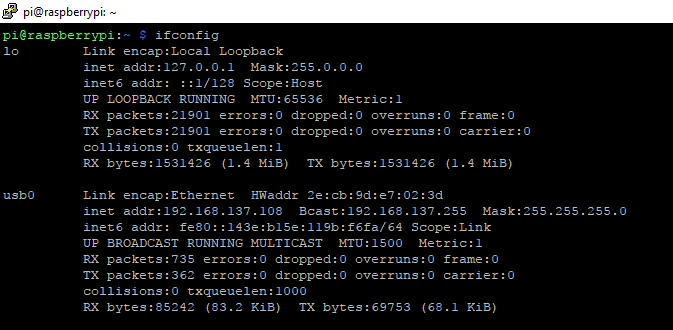
Run Ifconfig on your Raspberry Pi to check you have a routable IP address in the 192.168.x.x subnet.
Routable IP network address


Tuesday, 13 June 2017

Pimoroni HyperPixel

Something to Compare

HyperPixel 800x480
I've just picked up the HyperPixel screen from Pimoroni and it is a quality screen for the Raspberry Pi. I thought it would be good to post a bit about getting this up and running along with a comparison with the cheaper and bigger 5 inch HDMI  XPT2046 touchscreen that I got from eBay.

At the end of the day these screens are likely to be embedded (for me that I means glued) into most projects. The 7in official screen is available, but I feel it's just a bit too big for embedding and too small for development.

The HyperPixel fits in-between the cheap and expensive touchscreens. At the cheap end screens are resistive touch where as the top end are capacitive touch. A stylus is usually required for accurate touch on a resistive screen, although a finger nail can be an good enough substitute. Capacitive touch will pick up from a finger tip without much pressure on the screen.
The HyperPixel is a capacitive touch screen whereas the XPT2046 uses resistive. In my opinion each have their pros and cons. Resistive is good for single screen clicks but a bit poor for dragging and dropping type actions. Capacitive won't work through gloves or with a stylus (unless conductive), but is better for swiping and dragging.

HyperPixel

Setup of the HyperPixel is really straight forward. It's a single command install provided by Pimoroni. There are detailed instructions for manual installation if you like to know what's going on. 
I ran the simple one on a fresh Jessie install and it worked straight after reboot. Happy days compared to the XPT2046. 

Booting up to the desktop presents a really clear display with excellent viewing angles. I need to tilt the XPT2046 to see it clearly, whereas this is clear at all angles.
The screen fits in my Short Crust Plus case very neatly, but the lid or other extenders will not fit as the screen is in the way. 
Touch detection is accurate and works to the edges reliably which is also a plus against the cheaper XPT2046 which just doesn't like the edges.
In the packaging there is a nylon thread which is to support one side of the screen. I found this to be too long for use with a bare Pi 3 board and too short when used with a Pimoroni coupe case. There may be a bit of DIY to cut this down to size. The screen sits neatly on the USB ports so the support isn't really necessary.
Nylon Thread Support

The Pixel desktop isn't a touchscreen friendly environment and the small icons are a pain to access on the small 3.5'' display. You will see that I have a wireless keyboard and mouse attached and this is necessary for both screens to setup the software and quickly navigate in a browser. What this screen, and other small touchscreens need is a window manager like Android to really work with just touch. 

The HyperPixel screen connects using the DPI parallel display interface. This means that you lose the SPI and I2C capability. There are still free GPIO pins available but the ability to interface with these isn't straight forward when the screen is attached. Some research is needed to discover the available pins. In comparison the XPT2046 avoids this by connecting to the HDMI and keeping a lot of pins free for other components. 

XPT2046 5'' Display

This screen is the cheaper choice and at 5'' gives a bit more for your money. The viewing angle is poor and even a slight tilt reduces colour contrast. Colours are not as bright as the HyperPixel. On a plus point the bigger screen is better on the old eyesight for reading text.

Out of the box the screen is a bit fiddly to setup. A disc of instructions are provided and clear enough to step through with a bit of patience. It works with the latest Jessie install quite happily. A bit of tweaking is needed in config.txt to prevent to the overscan at the bottom of the screen.

As the screen connects up to the HDMI it refreshes as well as the HyperPixel. Touch response isn't as good and the accuracy is poor near the edges. Mouse and keyboard are still needed to manage Pixel.

Once connected the 40 pin header still has a lot of free pins to play with. Only the SPI and 2 GPIO pins are used. The screen actually only connects to 26 pins allowing jumper wires to squeeze in.
The screen also has a pass through for all 26 pins allowing another header to be attached to the back of the screen. 

What Does This Mean?

HyperPixel is a good high quality screen. If you want mobile phone quality then this is the one. 

Both screens are useless in my opinion for Pixel desktop. This isn't the fault of the screens and is more to do with Pixel being designed for mouse and keyboard. 
If you are coding up your own interfaces, for example in Pygame, then you can cater for the touchscreen inputs and have a great experience. This should open the doors to cool custom applications and games on the Pi.

Directly these screens are hard to compare. They are for different purposes and it will depend on what they will be running.

Overall the XPT2046 screen is better for people who want to add extra hardware and run a display. Attaching I2C devices or running stuff off the GPIO pins is much easier than the HyperPixel. 

HyperPixel appears to be for applications which need a clear screen and capacitive touch at a decent price.

Virtual Keyboard Setup

XVKBD on the HyperPixel
If you are determined to use the touchscreen then I'd recommend XVKBD
> sudo apt-get install xvkbd

Run the keyboard from the command line with 
> xvkbd &

Matchbox on the XPT2046

Another keyboard is Matchbox
> sudo apt-get install matchbox-keyboard

Run matchbox from the command line with 
> matchbox-keyboard &

Both keyboards work well, but the xvkbd has slightly larger buttons and is a bit easier to read and touch first time. Both are a bit clunky to use and will need scripting into the start up scripts to load automatically.

Modmypi has a quick post about Matchbox setup, but the principles are the same for xvkbd desktop icon setup as well.


Sunday, 30 April 2017

Raspberry Pi GPS

Raspberry Pi GPS

I covered a whole GPS solution using a Pi Zero in a previous post. This covered a lot of different components and the only one I haven't posted about is the GP-20U7 module for GPS.
This approach will also work for other GPS modules as GPSD supports lots of devices over serial UART and USB.
I've chosen the GP-20U7 basically because it's one of the cheaper options for GPS and it does a reasonable job. This GPS device provides information every second. GPS lock is a bit slow from cold start.
My post here will cover GPS usage using Python2.7 and not using other tools or languages.

Sadly the standard GPSD python library is just 2.7 but there are python 3 libraries ported outside the standard distro for the Pi.

GPS Installation

A couple of packages are needed to get GPS services up and running
> sudo apt-get install gpsd python-gps

There are some tools to see GPS on X and the command line.
Note that the clients will also install dependencies for X so I skip these for headless Pi Zero builds. If you would like to try them then install
> sudo apt-get install gpsd-clients

Edit /etc/defaults/gpsd. For the GP-20U7 module add info to the file
# Default settings for the gpsd init script and the hotplug wrapper.

# Start the gpsd daemon automatically at boot time
START_DAEMON="true"

# Use USB hotplugging to add new USB devices automatically to the daemon
USBAUTO="true"

# Devices gpsd should collect to at boot time.
# They need to be read/writeable, either by user gpsd or the group dialout.
DEVICES="/dev/ttyAMA0"

# Other options you want to pass to gpsd
GPSD_OPTIONS=""

Ensure the serial ports are enabled and the login shell is disabled.
Run raspi-config and access Advanced options
> sudo raspi-config

Select the Serial option.


When asked if you want the login shell accessible, answer No.
This removes references from the /etc/inittab and /boot/cmdline.txt.
The serial port should now be free for the GPS module to use.

Hardware Setup

Ensure there's no power to the hardware before plugging in the GPS module.

The image shows a Raspberry Pi Zero, but the 40 pin header is the same for Pi 2 and Pi 3 so the wiring is the same. 
Power to VCC is from the 3.3V pin. GND can connect to any group pin on the Raspberry Pi header. TX pin on the GPS module must connect to the RX pin on the Raspberry Pi.

The connector on the GP-20U7 is a JST female, and unless you have a male JST adapter the wires will need cutting to add whatever connector you need. I use 0.1 inch female crimped housing which can be found from various online vendors (linked to one vendor as an example).

Running GPSD

Executing the service requires enabling the service and socket. This will ensure the service runs on start-up. 
> sudo systemctl enable gpsd.service
> sudo systemctl enable gpsd.socket
> sudo systemctl start gpsd.service

The service will run and respond to requests for GPS data using the loopback interface (127.0.0.1) on the default port of 2947.
To change the interface and port the /etc/systemd/system/sockets.target.wants/gpsd.socket file can be updated with the required settings

Other Pi Issues

The year may be incorrectly displayed if the Pi clock hasn't been updated over NTP, set manually or maintained by a real time clock. I've not yet experimented with different clock settings for the GP-20U7 and it may or may not be an issue.

Example Code

All example code is for python 2.7.

None of the code is GP-20U7 specific. If you have a GPS module working with GPSD then this should work.

Each example is more advanced than the last. This should help you discover the appropriate level of code to start working from.

Python Example - 1

This example is about as simple as possible to test that GPSD is running as expected

import gps

gpsobj = gps.gps('127.0.0.1', 2947) ;
gpsobj.stream(gps.WATCH_ENABLE | gps.WATCH_NEWSTYLE)

try:
    for rpt in gpsobj:
        try:
            print rpt

        except StopIteration:
            # Attempt to restart
            gpsobj = gps.gps()
            gpsobj.stream(gps.WATCH_ENABLE | gps.WATCH_NEWSTYLE)

except:
    gpsobj.stream(gps.WATCH_DISABLE)

print ("\nTerminated GPS Example 1")

This spits out a report from the python gpsd library. There's a lot of information here and can take a bit of time to figure out what is what. There is detailed documentation for the gpsd_json data, which explains all of the output.

Note that gpsd requires a continuous loop to keep up and read data. Clients which do not read data before the stream buffer is full will be disconnected by the gpsd daemon. 

Python Example - 2

This example shows the extraction of TPV data, which is typically what you need for any GPS application as this record provides all the location, time and speed info.
In addition to this the SKY information is also read to provide some information on satellites, although this isn't essential.
All data fields cannot be assumed to be present and each needs to be checked.
The key field to check is the mode data field. Until this equals 2 or 3 the location isn't fixed.
When mode is 2 then the data is 2D information and although the location is fixed, there's no altitude data.
When mode is 3 then the data is 3D meaning all longitude, latitude and altitude is fixed.

import gps
import dateutil.parser

kmtomiles = 0.621371

info = {'mode':0,
        'gpstime':'',
        'error_time':0,
        'latitude':0,
        'longitude':0,
        'error_latitude':0,
        'error_longitude':0,
        'altitude':0,
        'error_altitude':0,
        'speedkm':0,
        'speedmiles':0,
        'error_speed':0,
        'climb':0,
        'error_climb':0,
        'satellites':0,
        'satellites_used':0}

gpsobj = gps.gps() ;
gpsobj.stream(gps.WATCH_ENABLE | gps.WATCH_NEWSTYLE)

# Print a header for values being displayed
print(str(info.keys()).strip('[]'))

try:
    while True:
        try:
            gpsdat = gpsobj.next()
            if gpsdat['class'] == 'TPV': # Read time-position-velocity data
                if hasattr(gpsdat, 'time'):
                    nix_time = dateutil.parser.parse(gpsdat.time)
                    info['gpstime'] = str(nix_time)
                if hasattr(gpsdat, 'ept'): info['error_time'] = float(gpsdat.ept)
                if hasattr(gpsdat, 'mode'): info['mode'] = int(gpsdat.mode)
                if hasattr(gpsdat, 'lat'): info['latitude'] = float(gpsdat.lat)
                if hasattr(gpsdat, 'lon'): info['longitude'] = float(gpsdat.lon)
                if hasattr(gpsdat, 'epy'): info['error_latitude'] = float(gpsdat.epy)
                if hasattr(gpsdat, 'epx'): info['error_longitude'] = float(gpsdat.epx)
                if hasattr(gpsdat, 'alt'): info['altitude'] = float(gpsdat.alt)
                if hasattr(gpsdat, 'epv'): info['error_altitude'] = float(gpsdat.epv)
                if hasattr(gpsdat, 'speed'):
                    info['speedkm'] = float(gpsdat.speed)
                    info['speedmiles'] = float(gpsdat.speed) * kmtomiles
                if hasattr(gpsdat, 'eps'): info['error_speed'] = float(gpsdat.eps)
                if hasattr(gpsdat, 'climb'): info['climb'] = float(gpsdat.climb)
                if hasattr(gpsdat, 'epc'): info['error_climb'] = float(gpsdat.epc)
            if hasattr(gpsdat, 'satellites'): # Read sky data
                satellites_used = 0
                for sat in gpsdat.satellites:
                    if hasattr(sat, 'used'):
                        if sat.used:
                            satellites_used += 1
                info['satellites'] = len(gpsdat.satellites)
                info['satellites_used'] = satellites_used
                
            print(str(info.values()).strip('[]'))
                
        except KeyError:
            pass # Ignore key errors
        except StopIteration:
        # Attempt to restart
            gpsobj = gps.gps()
            gpsobj.stream(gps.WATCH_ENABLE | gps.WATCH_NEWSTYLE)

except KeyboardInterrupt:
    gpsobj.stream(gps.WATCH_DISABLE)
    print ("\nTerminated GPS Example 2")

Python Example - 3

Let's get into something more advanced with a threaded GPS application. An application needs to constantly poll and consume GPSD data to keep up-to-date and prevent GPSD from closing the data stream. This is a bit problematic for applications that need to do other things like wait for user input. 
The solution is to run the GPS updates in the background and provide a utility to get position data when required.
This example provides a GPSWorker object which does all the hard work in another thread. At the end of the example you can see a simulated application which waits for user input.

Enter q to quit and any other input followed by Enter to print GPS data. This demonstrates an application that has to wait on other inputs and processing without concern about consuming GPS data.
The example here just extracts longitude, latitude and altitude, but any of the other data points can be read in an application. 

import gps
import dateutil.parser
from threading import Thread, Lock

class GPSWorker(Thread):
    def __init__(self):
        Thread.__init__(self)
        self.info = {'mode':0,
                     'gpstime':'',
                     'error_time':0,
                     'latitude':0,
                     'longitude':0,
                     'error_latitude':0,
                     'error_longitude':0,
                     'altitude':0,
                     'error_altitude':0,
                     'speedkm':0,
                     'speedmiles':0,
                     'error_speed':0,
                     'climb':0,
                     'error_climb':0,
                     'satellites':0,
                     'satellites_used':0}

        self.gpsobj = gps.gps() ;
        self.__quit = False
        self.__lock = Lock()
        self.__started = False 

    def start(self):
        self.gpsobj.stream(gps.WATCH_ENABLE | gps.WATCH_NEWSTYLE)
        if not self.__started:
            Thread.start(self)
        
    def stop(self):
        if self.is_alive():
            self.gpsobj.stream(gps.WATCH_DISABLE)

    def terminate(self):
        self.__quit = True

        # start the streaming again to unblock the wait
        self.gpsobj.stream(gps.WATCH_ENABLE | gps.WATCH_NEWSTYLE)
        if self.is_alive():
            self.join()
            self.__started = False

    def get_location_info(self):
        self.__lock.acquire()
        ret = self.info.copy()
        self.__lock.release()
        return ret
            
    def run(self):
        # Print a header for values being displayed
        #print(str(info.keys()).strip('[]'))
        kmtomiles = 0.621371

        while not self.__quit:
            try:
                gpsdat = self.gpsobj.next()
                self.__lock.acquire()
                if gpsdat['class'] == 'TPV': # Read time-position-velocity data
                    if hasattr(gpsdat, 'time'):
                        nix_time = dateutil.parser.parse(gpsdat.time)
                        self.info['gpstime'] = str(nix_time)
                    if hasattr(gpsdat, 'ept'): self.info['error_time'] = float(gpsdat.ept)
                    if hasattr(gpsdat, 'mode'): self.info['mode'] = int(gpsdat.mode)
                    if hasattr(gpsdat, 'lat'): self.info['latitude'] = float(gpsdat.lat)
                    if hasattr(gpsdat, 'lon'): self.info['longitude'] = float(gpsdat.lon)
                    if hasattr(gpsdat, 'epy'): self.info['error_latitude'] = float(gpsdat.epy)
                    if hasattr(gpsdat, 'epx'): self.info['error_longitude'] = float(gpsdat.epx)
                    if hasattr(gpsdat, 'alt'): self.info['altitude'] = float(gpsdat.alt)
                    if hasattr(gpsdat, 'epv'): self.info['error_altitude'] = float(gpsdat.epv)
                    if hasattr(gpsdat, 'speed'):
                        self.info['speedkm'] = float(gpsdat.speed)
                        self.info['speedmiles'] = float(gpsdat.speed) * kmtomiles
                    if hasattr(gpsdat, 'eps'): self.info['error_speed'] = float(gpsdat.eps)
                    if hasattr(gpsdat, 'climb'): self.info['climb'] = float(gpsdat.climb)
                    if hasattr(gpsdat, 'epc'): self.info['error_climb'] = float(gpsdat.epc)
                if hasattr(gpsdat, 'satellites'): # Read sky data
                    satellites_used = 0
                    for sat in gpsdat.satellites:
                        if hasattr(sat, 'used'):
                            if sat.used:
                                satellites_used += 1
                    self.info['satellites'] = len(gpsdat.satellites)
                    self.info['satellites_used'] = satellites_used
                                
            except KeyError:
                pass
            except StopIteration:
                # Attempt to restart
                self.gpsobj = gps.gps()
                self.gpsobj.stream(gps.WATCH_ENABLE | gps.WATCH_NEWSTYLE)
            finally:
                self.__lock.release()

# Main execution
if __name__ == "__main__":
    mygps = GPSWorker()
    mygps.start()
    try:
        while True:
            # Do stuff in your application
            # The application can call .start and .stop to control the gpsd stream

            # simulate stuff with user input
            response = raw_input("Type 'q' to quit and anything else to check GPS: ")
            if response == 'q' or response == 'Q':
                break

            # Where am I?
            info = mygps.get_location_info()
            if info['mode'] < 2:
                print ("No GPS lock")
            elif info['mode'] == 2:
                print ("2D Lock - LAT:{0}, LON:{1}".format(
                    info['longitude'],
                    info['latitude']))
            else:
                print ("3D Lock - LAT:{0}, LON:{1}, ALT:{2}".format(
                    info['longitude'],
                    info['latitude'],
                    info['altitude']))
            
    except KeyboardInterrupt:
        print ("") # skip over ^C
    except:
        mygps.terminate() # Call terminate to kill the thread
        raise
        
    mygps.terminate() # Call terminate to kill the thread

    print ("Application closing")


Closing Comments

GPSD does most of the hard work of reading the data from the hardware and converting it into a standard data stream. 
I've shown an example using a serial device connected to the 40 pin header. USB dongles can be found which should slot straight into a Pi and also work with the example code (you will need to use the serial /dev/ name instead of /dev/ttyAMA0)

GPS receivers also provide an additional feature for a Raspberry Pi because it also provides a clock source when your device is not connected to a real time clock or on a network. 

Thursday, 26 January 2017

MQTT sensor setup with Raspberry Pi

Message Queue for IoT

So there's nothing new about MQTT. It's been around since the 90's, but despite all of this I've just discovered it and thought I'd share, even if it's just as a note to self about the setup. 
It stands for Message Queue Telemetry Transport and you can read the Wikipedia about it to dig into it a bit more.

It is simply a publish/subscribe message bus, which means something writes whilst other things can pickup and read the 'published' data. MQTT is a small, lightweight protocol suitable for IoT data and low bandwidth/resource communications.

A bus could look like the above and may have multiple devices connected. For example a sensor may be on one device reading temperature, whilst the other device may do something such as triggering a light to turn on or switch on the heating. Another mobile device could operate as a dashboard to see what's going on. 
So what's the big deal? It could all be easily built with some direct connections and some web pages. 

Well the great thing about the bus is it's flexibility to add or remove devices. In the above example the sensor on the Pi Zero could be replaced with and Arduino sensor. A new dashboard device could be introduced to also relay the information to your TV or email inbox with a summary. Other devices could be added to react to temperature readings and open/close a window or do other things. 
All these changes are possible without rewriting point-to-point code and allows reuse of information.

Setting up

The first thing to setup is the server. This is fairly straight forward

Install the server from the command line
> sudo apt-get install mosquitto 

Install client tools
> sudo apt-get install mosquitto-clients

This should install a running server and add tools for some testing

Run a publish command to write to the bus
> mosquitto_pub -t test -r -m "Hello World"
This writes to a topic called "test" the value "Hello World" and retains the message

Next read the topic
> mosquitto_sub -t test
You should see Hello World

Clear the topic
> mosquitto_pub -t test -r -n
This writes a null message to the topic to clear it

Typically messages are not published as retained messages and would only be on the bus for subscribers to read and then deleted. For this test a retention was used because the mosquitto_sub command wasn't running at the same time as the mosquitto_pub.

Using an EnviroHat

The Enviro pHat is a good Pi Zero board to use for a practical test of MQTT. The Python code is really straight forward to use and there are multiple sensors to collect data.

The Python code can be installed with the following command
> sudo apt-get install python-mosquitto

This isn't the most up-to-date mosquitto, but it's the easiest to install for a demo. Look at the Eclipse paho project because the latest mosquitto code has been merged into there.

Adding PaPiRus

To provide a readable display the PaPiRus e-ink display has been added, but isn't essential for a test


Example Code

Prerequisites for the code
For the PaPiRus setup follow my post to setup. Edit the configuration to set the screen size to 2.0
> sudo nano /etc/default/epd-fuse
Change EPD_SIZE and save
Restart with
> sudo service epd-fuse restart

The Enviro pHAT can be setup by following the instructions from Pimoroni.

In the example below, change the string in the connect_async to your MQTT server IP or server
name. I used the code reference for paho.

Code:

from PIL import Image
from PIL import ImageDraw
from PIL import ImageFont
from envirophat import light, weather, motion
import time
from EPD import EPD
import mosquitto


WHITE = 1
BLACK = 0

def on_connect(client, userdata, rc):
        print("Connected with result code {}".format(rc))

def on_disconnect(client, userdata, rc):
        if rc != 0:
                print("Unexpected disconnection. Return {}".format(rc))
        else:
                print("Disconnected from server")

def write_text(draw, x, y, text, size):
        draw.text( (x, y) , text, font=font, fill=BLACK)

try:
        dis = EPD()
        dis.clear()
        text_size = 14

        client = mosquitto.Mosquitto()
        client.on_connect = on_connect
        client.on_disconnect = on_disconnect
        client.connect_async("mqtt.orbitalfruit")
        client.loop_start()

        font = ImageFont.truetype('/usr/share/fonts/truetype/freefont/FreeMono.ttf', text_size)
        image = Image.new('1', dis.size, 1)
        draw = ImageDraw.Draw(image)

        while True:
                l = 0
                rgb = light.rgb()
                temp = round(weather.temperature(),1)
                press = round(weather.pressure(),2)
                heading = motion.heading()
                lightstate = light.light()

                write_text(draw, 0, 0, "Temp: {}".format(temp), text_size)
                l += text_size
                write_text(draw, 0, l, "Pressure: {}".format(press), text_size)
                l += text_size
                write_text(draw, 0, l, "Colour R:{0},G:{1},B:{2}".format(rgb[0], rgb[1], rgb[2]), text_size)
                l += text_size
                write_text(draw, 0, l, "Heading: {}".format(heading), text_size)
                l += text_size
                write_text(draw, 0, l, "Light: {}".format(lightstate), text_size)

                dis.display(image)
                dis.partial_update()
                draw.rectangle([0,0,dis.width,dis.height], fill=1)

                client.publish("envirohat/temperature", temp)
                client.publish("envirohat/pressure", press)
                client.publish("envirohat/colour/red", rgb[0])
                client.publish("envirohat/colour/green", rgb[1])
                client.publish("envirohat/colour/blue", rgb[2])
                client.publish("envirohat/heading", heading)
                client.publish("envirohat/light", lightstate)
                time.sleep(10)

except KeyboardInterrupt:
        client.loop_stop()
        client.disconnect()

The client code publishes to the topic path "envirohat/". This is a useful way of grouping topics and forms a directory like structure.

Execute the code on the Pi Zero (note that it will need a network connection).

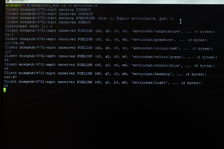
On your server you can type
> mosquitto_sub -t envirohat/#

The trailing # is a wildcard character to show all topics below the parent topic. This displays all values pushed to the bus by the Pi Zero.


Displaying to a Mobile Device

There are a few MQTT clients available across Andriod and Apple. 
MQTT Dashboard on Android provides a nice display. 
Configure the applications to point to the server and the topic of interest. I used 
envirohat/temperature 
envirohat/pressure
for testing


Take the Bus

This is just the basics, but the example creates something which can be used immediately for monitoring. Devices reading from the MQTT server can take actions and all the connecting devices can be built in a modular way. 

Monday, 5 December 2016

Nook Simple Touch

Resurrecting an old Nook Touch

In a quest to find some larger e-ink screens for projects I came across the Nook Simple Touch, which features a 600x800 e-ink touch screen.
I picked one up from eBay to potentially steal the screen, or at least hack an interface for a Raspberry Pi or Arduino.
As it happens, the 800MHz processor package isn't too bad to power your own projects. The wireless can hook up the screen to a network and provide an interface most projects without opening the back.

Getting the Nook working

If you are in the UK then B&N have stopped supporting the Nook devices on their book store. This also means you cannot register a device. The first hurdle to overcome is the registration to use the device. It's also a prerequisite to rooting. 

If you ask B&N nicely they will give you the following steps:
1. Turn on and wait for the welcome screen
2. Press the top right page turn button and at the same time swipe across the top of the screen (left to right)
3. The Factory button will appear. Press this to activate the factory settings screen
4. Hold down the same button as before (top right page button) and at the same time tap the bottom right of the screen.
5. A Skip Oobe button will appear as shown in the image below. Press this button.


You can now use the Nook Simple Touch without registration.

As it is the Nook can connect to a PC and PDFs or e-books can be uploaded to the device memory for reading on the screen.

Rooting

Rooting the device allows additional Android applications to be loaded, but don't expect to be loading up the latest apps from the store. The device only supports Android 2.1 and any potential hacks to upgrade will only get as far as Gingerbread.

Nook Manager is one of the many rooting apps available and I found it easy to use. It also allows an SSH server and/or a remote ADB to be run on the device.

I did have success installing the play store and logging in to my account. It does take some time to activate properly. The result were apps, which either crashed or were so old the services they used were no longer available. The BBC News app was the only one I could get working.

On the plus side the Nook Manager app is fairly easy to reverse engineer and is actually a good example to get started on custom code for the Nook Touch. Under the hood there's an Android Linux OS which will run code compiled for the ARM 7 processor so with a bit of cross compilation the device can be made to dance to your tune.

Custom code

Following the Nook Touch example and writing to the frame buffer directly allows 16 bit grey scale images to be displayed. For custom use none of the Android environment is needed. 
The great thing about the Nook is that it boots from the external SD card slot so custom kernels and ramdisk images can be loaded up without overwriting the old Nook system stored in internal memory. 

Managing the uRamdisk images requires a Linux system with dd and mkimage tools or a Window's tool can be downloaded called ImgUtil

Customise the init.rc start up script to run anything you want at start-up. Nook Manager runs a system_ready script when booted.

Example code on the Nook

A little application I've written provides weather reports from Open Weather Map on the Nook screen. 
This writes to the frame buffer directly, reads ZForce inputs from the touch screen and reads inputs from the buttons around the screen.
All code can be found in GitHub at https://github.com/AidanHolmes/NookDisplay. This also uses the graphics library at https://github.com/AidanHolmes/graphicslib

It's cold but maybe not that cold openweathermap

Sunday, 16 October 2016

Revisiting Sparkfun Colour LCD

Python for Sparkfun Colour LCD

Some time ago I posted code and setup notes to get the Nokia6100 screens, featuring on the Sparkfun Arduino shield, working on a RaspberryPi.
The examples were written in C/C++. This isn't so useful when the majority of users are working with Python so I decided to revisit and provide a useful object class to handle the display.

Setup

The shield is configured to fit straight on top of the Arduino. This doesn't mean it cannot work on other platforms. A bit of creative use of jump leads can get this working quite as effortlessly on the Pi.
The obvious connections are to 3.3V, 5V and GND. 
The other pins go to SPI (ensure it's enabled on your Pi in raspi-config).

From the shield connect:
Pin 13 (Clock) to 11 (SCLK) on a Pi
Pin 11 (MOSI) to 9 (MOSI) on a Pi
Pin 9 (CS) to 8 (CS0) on a Pi
Pin 8 (Reset) to any free GPIO of your choice. I used 25

The 3 buttons are connected to 3, 4 and 5 on the shield. I'm not going to cover the buttons here as it's another topic. RPi.GPIO library provides everything you need to get them working.

Software for the Raspberry Pi

Python code for the Pi can be found on my GitHub site at https://github.com/AidanHolmes/Nokia6100.

The code hasn't been made into a module or anything fancy.

from nokia import Nokia6100
should be enough to create the connection and send PIL images to the 132x132 LCD display.

This works on the shields with the Philips PCF8833 display as this is the variant I have. Code for the Epson display is included, but not tested. Start up sequence and code for the Epson is mostly borrowed from Jame P. Lynch's code on the Sparkfun site in Nokia LCD Display Driver.pdf.

Quick Start

from nokia import Nokia6100
from PIL import Image

disp = Nokia6100(25) # Assuming SPI bus 0 and CS0 used
disp.initialise()

img = Image.open('myimg.jpg')
disp.display(img)

Reference

The interface for the Nokia6100 class can be found on the GitHub page. It's quite a small set of functions. PIL does all the hard work with images so the functionality is just about the hardware control. 

Performance

The C/C++ code pushes data over SPI faster than the Python. It's fairly marginal and both the Python and C/C++ code can be seen to redraw the display. The redraw is more apparent using Python whilst the C/C++ code is a quick flicker. 
I'm not quite sure what the real speed is over the Raspberry Pi's SPI, but I expect that the real speed isn't the max speed set in spidev.

In any case, I wouldn't expect the LCD to handle rapidly changing displays very well with user-space code driving the display.

Tuesday, 30 August 2016

pHat Stacking

Hat Stacking Pimoroni pHats

Pimoroni sell the Enviro pHAT, which is a really good little package to go on top of a Raspberry Pi. 

I was looking around for a temperature and humidity sensor and this has all of that plus motion, colour and analogue. I'm not sure how all of these can be used together but even separately these components can cost you more in separate breakout boards so not much loss to only use 1 or 2 of these features.

Combined with Scroll pHAT


The Scroll pHAT is great for text. Combined with the Enviro pHat this can show temperature, heading, pressure and motion.

The video shows the motion sensors reaction to being moved in the x and y axis. The dot can be thrown around which is a fun bit of code. 

Combined with Unicorn pHat


The Unicorn pHAT is just a colour frenzy. Text can be displayed, but this is fairly limited due to only having 4 LEDs high to play with.  
To show the light/colour sensor I sent the values directly to the Unicorn pHat.

Blue

Green

Red

Yellow
The camera doesn't pick the colours up as clearly as they were shown. The colours weren't correct for green and this showed up as a blue colour, but quite fun to play around with.