Saturday, 12 January 2019

Video Droid

Python Augmentation on Wheels


The project's aim is more about augmented reality experience than building a robot.
For me this is a new challenge to drive motors and communicate with a robot using a Raspberry Pi.
I'll break up the build into the following parts with some detailed information on linked pages to dive into this further
  • Hardware for Droid
  • Camera streaming from Raspberry Pi
  • Motor control, including hooking up an Arduino to Pi
  • Communication with Raspberry Pi
  • PyGame augmentation
Tools of choice are:
  • Raspberry Pi Zero W and Arduino Pro Mini 328
  • Sparkfun Motor Driver
  • Pimoroni's VL53L1X sensor
  • Adafruit 500 PowerBoost Charger
  • Sparkfun Fuel Gauge
  • 2200mAh LiPo battery
  • Python to just get things done. Loads of libraries for powerful functionality
  • PyGame and SDL to create a remote view of the droid
  • OpenCV required to do some of the video heavy lifting
  • Raspivid for streaming video. This is standard with the Raspberry Pi
  • Netcat to manage the video streaming from Raspberry Pi

Hardware for Droid

Tracks are on the Pololu Zumo Chassis which is fairly compact to add micro-motors and batteries for 6v supply. 
Zumo chassis and attached control box. Blue tack in good use to hold camera and TTF sensor

Pi Zero has been used as it's compact and can still use the standard Pi Camera (with different cable). Power usage is also much lower, which is better for the LiPo supply. 

Adafruit 500 PowerBoost combines well with the Sparkfun Fuel Gauge. A battery can be added to either holder (but not 2 batteries in both!), be charged and provide power. I added the USB connector to run a standard USB cable to the Pi. This means the protection circuits on the Pi are used. 
500 PowerBoost with soldered on Fuel Gauge

Getting everything in the box was very snug. As the Pi Zero only uses 2/3 of the width there is still room for the LiPo
Snug battery fits below the prototype board
Rotary encoders are fitted to both motors, but the faff with the soldering and fitting wasn't worth it in the end. The idea was to provide better control and detect stalling, but it was more a curiosity than a practical need. I get random inputs from the light sensors through the Arduino so given up for now. The majority of wires in the photos are from the encoders. Each motor adds an extra 4 wires which aren't really useful. 

Taking a recharge break with the lid off


Camera streaming

Raspivid comes installed with Raspbian images. There are other alternatives such as Gstreamer which require additional install and setup. I will try out Gstreamer, but for now the results from Raspivid are good enough.

With an attached camera on the Raspberry Pi run the following
raspivid -t 0 -fps 15 -w 640 -h 480 --inline -b 10000000 -n -o - | nc -lk -p 5001

Options
  • -t 0 creates a continuous output
  • -fps 15 sets the framerate to a slow 15, this is slow enough to prevent buffering
  • -w 640 -h 480 sets the desired resolution to send. This is reasonable for speed and quality
  • -inline ensures that the video can be resumed by the connecting Pygame code
  • -b 100000000 sets the bit rate
  • -n to prevent showing a preview
  • -o output to stdout
  • nc is a pipe of the output to netcat
  • -lk listen for connections and keep open after disconnects
  • -p 5001 listen on port 5001
I tested the stream Mplayer. Download and install to the client machine. Netcat is also required to feed the stream into Mplayer.
Netcat is provided in the NMAP package for Windows download at https://nmap.org/download.html.

OpenCV can process an incoming video stream. Opening the stream is as simple as
cam = cv2.VideoCapture("tcp://192.168.1.10:5001")


Add the IP name of the Raspberry Pi with attached camera into the connection string.

Processing images for Pygame is easy with the following code
import cv2
import pygame

pygame.init()
screen = pygame.display.set_mode((640,480))
cam = cv2.VideoCapture("tcp://192.168.1.10:5001")
while True:
  ret, image= cam.read()
  pygame_surface_image = pygame.image.frombuffer(image.tostring()[::-1], image.shape[1::-1], "RGB")
  screen.blit(pygame_surface_image,(0,0))
  pygame.display.flip()

Camera images take some time to catch up, but once in sync then there's only a small amount of lag.

Motor control

Micro motors controlled by Spark Fun Motor Driver which provides H-Bridge control for each motor. 
Controlling of motors from a Raspberry Pi is completely possible, but I've had problems with PWM on GPIO 18 when the processor is even slightly busy. Arduino controllers are much better at PWM control as they provide real-time processing so the Pi works with a Sparkfun Pro Mini 328 running at 5v. 

The Arduino and Raspberry Pi run at different voltages, so communication over serial requires a voltage drop from 5v to 3.3v. This is achieved with a voltage divider. Only the TX and RX need connecting to talk to the Arduino. Programming is possible from the Pi but the reset button will need pressing at the right time to upload code.
More information can be found on my Pi to Arduino page.

Serial communication with commands to move the motors in 2 directions and at different speeds. On a Raspberry Pi Zero the serial device runs on /dev/serial0

Communication with Raspberry Pi

The Zero W is great with its WiFi capability. Streaming video over this link is ideal. Video has already been mentioned above, but the other communication to issue move commands, activate LEDs and use the Time-to-Flight sensor need an interface.
MQTT jumps to mind immediately as I've used this before for sensors. This is great for a publisher and subscriber situation but REST APIs may fit this a little better (I'm still thinking of providing a hybrid with an MQTT bus as well for future changes). 

REST APIs can be provided using Connexion and Flask. I use python 3 for all my new code so it's referenced in the installations below:
sudo apt-get install python3-flask
sudo pip3 install connexion
sudo pip3 install connexion[swagger-ui]

A client machine (running the PyGame software) will need the Python package requests:
pip install requests

The following API end points are created

  • /droid/range provides feedback and configuration of the VL53L1X time-to-flight sensor
  • /droid/battery provides capacity information
  • /droid/move allows specification of move commands to Arduino 
  • /droid/lights illuminates LED headlights
With the swagger-ui installed for Connexion the API can be used by browsing to /droid/ui. This provides a nice interface to set and query values. 

PyGame Augmentation

This is the fun part. A client machine (Windows or another Raspberry Pi on Linux) can connect to the Video Droid and control it. 
I made the display appear like you are viewing through the windows of a vehicle. 
Control view with HUD and control panel
Pressing the Video button connects the video stream from the Raspberry Pi droid. Ranging information appears as a HUD overlay
Land of the giant hands
All button presses send a command over REST to the API end points hosted by Flask. Some polling has to happen to get the range distance information. This may have been better over a MQTT bus.
There is also a battery level indicator (not shown as battery wasn't in use for the shots) which appears when running on LiPo power. See the video at the start of this post for an internal and external view of the Video Droid.

I'm currently having loads of fun driving this around the house and making obstacle courses for it to explore. There will be another droid in the pipeline to explore OpenCV further and hook up NoIR camera for night vision. 

Saturday, 8 December 2018

PyGame on Nook Simple Touch

PyGame app launcher

Building the PyGame app launcher was the most simple part of this hack for the Nook Simple Touch. Rebuilding the Linux OS to build Python was actually a long job which I almost gave up on. I'll get into the OS later. 

I'm starting with the PyGame launcher as it's the heart of this build. Here's a video from boot up


Star field running on Nook
The launcher runs on x86 Linux and Raspberry Pi operating systems, but the code is tailored for an e-ink screen. Refresh rates are very slow compared to an LCD display and only 10 FPS really work on the Nook display. Due to the slow refresh rates all the apps are written to prevent screen blurring as much as possible. 

Although PyGame sounds like it should be just for games, it actually provides a basic graphics environment to create all kinds of apps. I've written 2 basic apps to establish a framework for future apps. One is a basic system status app with text on the screen and the other is a star field app with animated graphics and screen interaction. Both of these require different demands and the launcher framework can handle both with varied framerate support.

System status app
The 2 screen shots of the apps can be seen here. Note that the star field app takes all the CPU, but the system status (and the launcher app itself) only take up 22% or so as it only needs to update once per second. Apps can specify the framerate they require in the app config. 

Initially the code was all written in a single thread as this reduces the potential race condition bugs found in threaded apps. Polling the user input is highly demanding of the CPU so a separate thread was introduced to remove the polling and throttle back the CPU when its not required.

PyGame App Framework
Apps run one at-a-time and when they are closed they are deleted to free up memory and CPU. This keeps down overheads, but if background apps are needed in the future it should be fairly simple to change the launcher to manage these as well as a foreground app.

Getting Python on the Nook

The Nook Simple Touch from Barnes & Noble boots from an SD card. Some smart folk created rooting apps using this ability to boot up the Nook and modify the Android OS. I've used the same method to create a bootable OS which doesn't interfere with the original software installed on the Nook

Kernel source code is still available from Barnes & Nobel to download. This doesn't cross compile with new gcc cross-compilers. The only solution I could find was to track down an old compiler.
From this point a new u-boot and kernel can be built.
Soldered serial port access
With a bit of soldering the serial ports can be accessed to debug the new kernel and OS startup scripts. Modifications of u-boot startup are required to direct the console. I connected up with a ribbon header allowing easy disconnection and ability to close the case up. The XDA forums are still full of archived posts from years ago that outline the process to modify kernels and u-boot. I won't get into it here.

Building glibc, binutils and gcc on the Nook really broke the back of the OS build. Once these are in-place all the other libraries can be built on the Nook including Python.
I've opted to build Python 3.7 instead of 2.7 as hosting both shouldn't be necessary. SDL 1.2 is needed as PyGame doesn't yet support SDL 2. 
SDL 1.2 requires a minor modification to the fbcon driver because the e-ink driver doesn't support double buffer panning. Instead the display is flipped with a call to FBIOPUT_VSCREENINFO changing the yoffset. 

The USB port on the Nook is a gadget and host controller. There is limited ability to plug in a keyboard and I've had this working, but the device isn't really spec'd to be a host and it's very unreliable. There's not enough power to light up the keyboard LEDs.
As a gadget I've configured the kernel to be a serial device and a login prompt is attached to this so login access can be granted to a Nook reader if Wifi is unavailable. 

What is next?

  • Providing a downloadable image of the SD card would be great to share the OS build. It will be large so figuring out where to host it will be the problem
  • UI for wpa_configure is needed to change WiFi network access. Currently Wifi config requires editing of text files
  • Write a few more apps to demo the framework
  • Port an existing pygame e-reader app to work on the Nook, after-all this is an e-reader device


Sunday, 11 February 2018

Hyperpixel Touch Dashboard

Revisting Pimoroni Hyperpixel

This is a really nice little display that fits neatly onto any Raspberry Pi. It's sharp and responsive which is great for any interactive application. 

When I first received this I was a little disappointed that the screen took over so many of the header pins and Raspbian is pretty awful to use with a touchscreen. This got me thinking that what this screen is shouting out for is custom touchscreen applications that combine with the power of the Pi. 

Dashboarding on Raspbian

A little project of mine was focused on using the Pillow (PIL) Python library to draw custom graphs, controls and indicators for the e-ink displays. I put this aside, but reused and expanded the code to work with TK. I guess I could have gone in two other directions as well and used Pygame or Qt. I made a choice and used TK as Python seems closely associated. 

My main need was to display metrics and have limited button pressing capability. Luckily text input isn't an important requirement, although a decent on screen keyboard would be useful. 

Beer Brewing Dash

Beer brew stats are already captured in MQTT and are to hand on my phone. Why not on my desktop and on the HyperPixel. Well here's the results so far running on a Pi 3

This runs on Python 3 and 2.7 without any fuss. Linux distros will need to have some freefonts installed. The above is using FreeSans. 

Running on Windows is also possible and I've installed Python 3 to do just this. 

There's loads of configuration with the controls and the above are configured to be black on white whilst the HyperPixel is running with a black background.

The code is mostly there and should be up on GitHub soon. 


Thursday, 16 November 2017

Techno Beer

Pi and Beer

Not satisfied with just being a simple home brewer I decided to hook up a Raspberry Pi to control the temperature of my beer fermentation. Pretty useful when I'm too lazy to go into the garage, at work or just wanting to show off some real-time home automation. 

In this post I go through how I did this and the technologies used. This is no Craft Beer Pi setup, but it's a good jumping off framework guide.


OK, this isn't yeast, but it is beer related

What's in it?

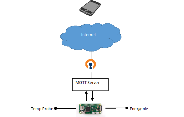
Basically I used OpenVPN, MQTT, Energenie and the reasonably priced DS18b20 temperature probes to build this.


OpenVPN is simple using the software at PiVPN. I don't think I need to elaborate on this much further as it isn't strictly beer related, but it does allow connection to your internal MQTT.

For MQTT just setup the Mosquitto server with:
> sudo apt-get install mosquitto

This gets the main servers installed and running. It's basic and with no authentication, but it will be there.

Energenie sell the Pi-Mote board which fits onto the pins of any Raspberry Pi. Example Python and instructions are on the Energenie site. My own code for the beer control implements a simple Python class to wrap the GPIO calls required to control the power sockets.
I did contemplate and even bought a set of relays to switch mains power and then realised I'd be crazy to mess about with mains voltage in a hobby project. Energenie have done the risky work and packaged it into a remotely controlled solution. 

The DS18B20 is a popular probe to use with liquids so I bought a pack of these on Amazon. These are inserted into the beer so a food grade heat shrink is required. Adafruit have exactly the heat shrink needed.

I avoided messing around with strip boards or bread boards and used the excellent ProtoZero board from ProtoBoards

Build the Pi

Disassembled view
The Pi-mote doesn't need any additional work to operate on the Pi. Just plug in and it's ready to go. The Energenie plugs into the top set of 26 pins which makes it compatible with early Raspberry Pi boards.

Incorporating the temperature probe only requires 3 pins and a 4.7k ohm resistor to work (3.3V power, ground and GPIO pin 4). Multiple probes can be chained off pin 4. I've used JST connectors to allow disconnection of the probes when not in use and to allow easy cleaning.


A stacking header is needed to provide pins to the Pi-mote board. Pin 4 isn't required by the Pi-mote and doesn't interfere with the Dallas 1-wire protocol used by the temperature probe.

Assembled boards and sensor
I've used the Pi Zero W for this project as it has all the wireless connectivity built in. 
Beer environments involve liquid so it's also wise to move the exposed hardware into a food container.

The ProtoZero board has ample room to expand the number of temperature probes that can be supported as can be seen in the Fritzing image below.
ProtoZero with 2 probes

2 probe extension in action

Energenie sockets

A commercial solution to DIY electrocution. Powertails also exist for 120V. I'm in the UK and the Adafruit switches wouldn't work so this is the next best thing. 

Setup is very simple. Plug in and press and hold the green button until the light flashes. This is set to program mode. Send an "on" signal to associate with the Pi-mote. The programs are remembered even after disconnection from mains power.

I plugged this into the heating mat for the beer fermenter bucket.
With the Python code running this is switched "on" to add heat and "off" when the temperature is at the max level.

The Pi-mote can control up to 4 sockets which is more than enough for beer!

Dashboard

Once all data is going into MQTT then getting the results out is really easy. 
Android has MQTT Dash and MQTT Dashboard in the app store. I like the look of MQTT Dash the best for viewing my beer temperature. iOS doesn't seem to have may MQTT apps which work as well as these but I'm keeping an eye out.

Both apps take in a topic and allow read and write access to the data. Metrics such as temperature readings are read-only whilst configuring the heaters can be write access to switch on/off. The apps need configuring to show what you are interested in and how you would like to view the information. It's fairly quick to do and once setup the dashboards can be viewed easily.

MQTT Dashboard Subscriptions

MQTT Dashboard Publishing

MQTT Dash growing Lactobacillus (high temp)

MQTT connection

MQTT provides a message bus to publish and subscribe messages. It's light weight and built for IoT devices.
Development of applications is quick and easy with many supported development languages as well as shell scripting.

A service bus provides a logical disconnect between the presentation layer (UI) and device data. Data on the bus can also be consumed by other devices or applications to provide further automation or new services.
For example; if the service was to go offline a watchdog application could send an email or text to alert that the device needs attention.

Connections can be encrypted and access to the server secured if you are worried of someone stealing data or turning devices on and off without your permission.

Code example

Control is really simple and my code is available on GitHub at https://github.com/AidanHolmes/beerpi.

This provides Python class wrappers for the Energenie and DS18B20 temperature sensors along with a control program to manage temperature using MQTT. 

Saturday, 7 October 2017

GPS logger and Google Maps


It has been a while since I posted about the Raspberry Pi Zero, PaPiRus and GPS logger.
Since the post I've updated further with a web service for displaying routes with Google maps. I actually use this GPS logger a lot when I'm out and about walking. This means I'm keeping it up-to-date for my own use, which I hope others also find useful.

I could represent the routes on the e-ink screen directly, but a squiggly line on a small screen just isn't going to be as good as a plot on a proper mapping service. All the important questions asked in the pub at the end of a walk are answered on the device screen, such as how far you've gone, for how long and the pace. The map plots are good for recalling an old route or recalling the point you go lost. 

Check out the previous post with details on the original build. 

All code can be cloned from GitHub at https://github.com/AidanHolmes/gpstracker

My implementation uses the original Pi Zero without the wireless or bluetooth from the W version. A wireless Zero makes connection to the web interface much more straight forward, but be aware of security implications running on public WiFi. 

Mapping GPS Routes

All logs are stored on the SD card and read by the web interface.
From the main screen the stored routes are listed with summary info. Summary information is built on this screen so it can take a bit of time to show as log files do not yet save this summary info in the logs.
Root view of all logs

Clicking on a stored route takes you to the Google Map screen and shows a plot of where you went. 

Single route - Helvellyn Walk
Here's an example of a walk up Helvellyn in Cumbria. 
Clicking on the start icon for any route shows distance and time.

Multiple routes are also shown on the map.
Multi-route GPS log
This is example of a log which contained 2 routes. Different colours are used and the start-end markers have different numbers. 
A single log can hold multiple routes when the log button is pressed and held to start and stop logging.

Implementation

Python Flask is used to display the web service from the Pi Zero. It keeps things fairly small and simple.

A Google Maps API key is required. They are free to register one so if you are using my code then add to config.py your own key. For example:
webconfig = {
    'interface' : '0.0.0.0',
    'port' : 80,
    'googlekey' : 'BBffSyUUP6agt11EblRT-123sdddFFAD'
}

Start the web interface
> python gpstracker/web.py

Access the root web page of your Raspberry Pi by entering the IP address into your browser. 
Logs are read from the logdir location as specified in config.py.

Read the web.py code for an example of how the TrackerGPS object is used to read data from a log file.

To get data from a file into an instance of TrackerGPS, each log line (JSON) needs feeding into a data entry with a call to data.gps_serial_data. Once the data is loaded it can be commited to as an entry with a call to data.commit_data(). Loop around to load all lines and then the TrackerGPS object can be queried for summary data. 

Alternatively a log file can be read with a call to readsessionlog(openfile, filterrecords=filt). This reads the log and returns an array of the GPSSummary objects, with one for each session.

Enabling Ethernet Gadget on a Zero

The Pi Zero with its Gadget USB feature is awesome to hook up to a PC and extend the features with a web interface. Note that the non-zero Pis up to the Pi 3 do not have a gadget USB and this will not work.
Simply add the following to your /boot/cmdline.txt and it will function as a network device in Windows when plugged into the USB port.

modules-load=dwc2,g_ether

For full instructions check out the latest configuration requirements with a quick Google search.
Adafruit have a tutorial here.

Connection sharing

RNDIS devices on a Windows OS are a bit tricky to get working first time. Connection sharing must be enabled to allow the Raspberry Pi to connect through to Google Maps. 
Plugging in the USB will not immediately grant a IP address to the Raspberry Pi. It can take a few minutes for the Pi to acquire a new address. On top of this Windows sometimes need persuasion by disabling and re-enabling the connection sharing to the RNDIS device

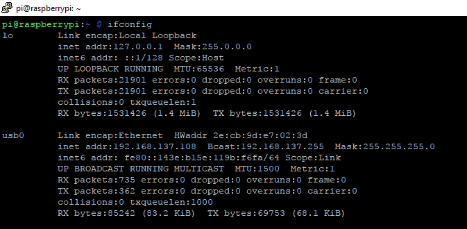
Run Ifconfig on your Raspberry Pi to check you have a routable IP address in the 192.168.x.x subnet.
Routable IP network address


Tuesday, 13 June 2017

Pimoroni HyperPixel

Something to Compare

HyperPixel 800x480
I've just picked up the HyperPixel screen from Pimoroni and it is a quality screen for the Raspberry Pi. I thought it would be good to post a bit about getting this up and running along with a comparison with the cheaper and bigger 5 inch HDMI  XPT2046 touchscreen that I got from eBay.

At the end of the day these screens are likely to be embedded (for me that I means glued) into most projects. The 7in official screen is available, but I feel it's just a bit too big for embedding and too small for development.

The HyperPixel fits in-between the cheap and expensive touchscreens. At the cheap end screens are resistive touch where as the top end are capacitive touch. A stylus is usually required for accurate touch on a resistive screen, although a finger nail can be an good enough substitute. Capacitive touch will pick up from a finger tip without much pressure on the screen.
The HyperPixel is a capacitive touch screen whereas the XPT2046 uses resistive. In my opinion each have their pros and cons. Resistive is good for single screen clicks but a bit poor for dragging and dropping type actions. Capacitive won't work through gloves or with a stylus (unless conductive), but is better for swiping and dragging.

HyperPixel

Setup of the HyperPixel is really straight forward. It's a single command install provided by Pimoroni. There are detailed instructions for manual installation if you like to know what's going on. 
I ran the simple one on a fresh Jessie install and it worked straight after reboot. Happy days compared to the XPT2046. 

Booting up to the desktop presents a really clear display with excellent viewing angles. I need to tilt the XPT2046 to see it clearly, whereas this is clear at all angles.
The screen fits in my Short Crust Plus case very neatly, but the lid or other extenders will not fit as the screen is in the way. 
Touch detection is accurate and works to the edges reliably which is also a plus against the cheaper XPT2046 which just doesn't like the edges.
In the packaging there is a nylon thread which is to support one side of the screen. I found this to be too long for use with a bare Pi 3 board and too short when used with a Pimoroni coupe case. There may be a bit of DIY to cut this down to size. The screen sits neatly on the USB ports so the support isn't really necessary.
Nylon Thread Support

The Pixel desktop isn't a touchscreen friendly environment and the small icons are a pain to access on the small 3.5'' display. You will see that I have a wireless keyboard and mouse attached and this is necessary for both screens to setup the software and quickly navigate in a browser. What this screen, and other small touchscreens need is a window manager like Android to really work with just touch. 

The HyperPixel screen connects using the DPI parallel display interface. This means that you lose the SPI and I2C capability. There are still free GPIO pins available but the ability to interface with these isn't straight forward when the screen is attached. Some research is needed to discover the available pins. In comparison the XPT2046 avoids this by connecting to the HDMI and keeping a lot of pins free for other components. 

XPT2046 5'' Display

This screen is the cheaper choice and at 5'' gives a bit more for your money. The viewing angle is poor and even a slight tilt reduces colour contrast. Colours are not as bright as the HyperPixel. On a plus point the bigger screen is better on the old eyesight for reading text.

Out of the box the screen is a bit fiddly to setup. A disc of instructions are provided and clear enough to step through with a bit of patience. It works with the latest Jessie install quite happily. A bit of tweaking is needed in config.txt to prevent to the overscan at the bottom of the screen.

As the screen connects up to the HDMI it refreshes as well as the HyperPixel. Touch response isn't as good and the accuracy is poor near the edges. Mouse and keyboard are still needed to manage Pixel.

Once connected the 40 pin header still has a lot of free pins to play with. Only the SPI and 2 GPIO pins are used. The screen actually only connects to 26 pins allowing jumper wires to squeeze in.
The screen also has a pass through for all 26 pins allowing another header to be attached to the back of the screen. 

What Does This Mean?

HyperPixel is a good high quality screen. If you want mobile phone quality then this is the one. 

Both screens are useless in my opinion for Pixel desktop. This isn't the fault of the screens and is more to do with Pixel being designed for mouse and keyboard. 
If you are coding up your own interfaces, for example in Pygame, then you can cater for the touchscreen inputs and have a great experience. This should open the doors to cool custom applications and games on the Pi.

Directly these screens are hard to compare. They are for different purposes and it will depend on what they will be running.

Overall the XPT2046 screen is better for people who want to add extra hardware and run a display. Attaching I2C devices or running stuff off the GPIO pins is much easier than the HyperPixel. 

HyperPixel appears to be for applications which need a clear screen and capacitive touch at a decent price.

Virtual Keyboard Setup

XVKBD on the HyperPixel
If you are determined to use the touchscreen then I'd recommend XVKBD
> sudo apt-get install xvkbd

Run the keyboard from the command line with 
> xvkbd &

Matchbox on the XPT2046

Another keyboard is Matchbox
> sudo apt-get install matchbox-keyboard

Run matchbox from the command line with 
> matchbox-keyboard &

Both keyboards work well, but the xvkbd has slightly larger buttons and is a bit easier to read and touch first time. Both are a bit clunky to use and will need scripting into the start up scripts to load automatically.

Modmypi has a quick post about Matchbox setup, but the principles are the same for xvkbd desktop icon setup as well.


Sunday, 30 April 2017

Raspberry Pi GPS

Raspberry Pi GPS

I covered a whole GPS solution using a Pi Zero in a previous post. This covered a lot of different components and the only one I haven't posted about is the GP-20U7 module for GPS.
This approach will also work for other GPS modules as GPSD supports lots of devices over serial UART and USB.
I've chosen the GP-20U7 basically because it's one of the cheaper options for GPS and it does a reasonable job. This GPS device provides information every second. GPS lock is a bit slow from cold start.
My post here will cover GPS usage using Python2.7 and not using other tools or languages.

Sadly the standard GPSD python library is just 2.7 but there are python 3 libraries ported outside the standard distro for the Pi.

GPS Installation

A couple of packages are needed to get GPS services up and running
> sudo apt-get install gpsd python-gps

There are some tools to see GPS on X and the command line.
Note that the clients will also install dependencies for X so I skip these for headless Pi Zero builds. If you would like to try them then install
> sudo apt-get install gpsd-clients

Edit /etc/defaults/gpsd. For the GP-20U7 module add info to the file
# Default settings for the gpsd init script and the hotplug wrapper.

# Start the gpsd daemon automatically at boot time
START_DAEMON="true"

# Use USB hotplugging to add new USB devices automatically to the daemon
USBAUTO="true"

# Devices gpsd should collect to at boot time.
# They need to be read/writeable, either by user gpsd or the group dialout.
DEVICES="/dev/ttyAMA0"

# Other options you want to pass to gpsd
GPSD_OPTIONS=""

Ensure the serial ports are enabled and the login shell is disabled.
Run raspi-config and access Advanced options
> sudo raspi-config

Select the Serial option.


When asked if you want the login shell accessible, answer No.
This removes references from the /etc/inittab and /boot/cmdline.txt.
The serial port should now be free for the GPS module to use.

Hardware Setup

Ensure there's no power to the hardware before plugging in the GPS module.

The image shows a Raspberry Pi Zero, but the 40 pin header is the same for Pi 2 and Pi 3 so the wiring is the same. 
Power to VCC is from the 3.3V pin. GND can connect to any group pin on the Raspberry Pi header. TX pin on the GPS module must connect to the RX pin on the Raspberry Pi.

The connector on the GP-20U7 is a JST female, and unless you have a male JST adapter the wires will need cutting to add whatever connector you need. I use 0.1 inch female crimped housing which can be found from various online vendors (linked to one vendor as an example).

Running GPSD

Executing the service requires enabling the service and socket. This will ensure the service runs on start-up. 
> sudo systemctl enable gpsd.service
> sudo systemctl enable gpsd.socket
> sudo systemctl start gpsd.service

The service will run and respond to requests for GPS data using the loopback interface (127.0.0.1) on the default port of 2947.
To change the interface and port the /etc/systemd/system/sockets.target.wants/gpsd.socket file can be updated with the required settings

Other Pi Issues

The year may be incorrectly displayed if the Pi clock hasn't been updated over NTP, set manually or maintained by a real time clock. I've not yet experimented with different clock settings for the GP-20U7 and it may or may not be an issue.

Example Code

All example code is for python 2.7.

None of the code is GP-20U7 specific. If you have a GPS module working with GPSD then this should work.

Each example is more advanced than the last. This should help you discover the appropriate level of code to start working from.

Python Example - 1

This example is about as simple as possible to test that GPSD is running as expected

import gps

gpsobj = gps.gps('127.0.0.1', 2947) ;
gpsobj.stream(gps.WATCH_ENABLE | gps.WATCH_NEWSTYLE)

try:
    for rpt in gpsobj:
        try:
            print rpt

        except StopIteration:
            # Attempt to restart
            gpsobj = gps.gps()
            gpsobj.stream(gps.WATCH_ENABLE | gps.WATCH_NEWSTYLE)

except:
    gpsobj.stream(gps.WATCH_DISABLE)

print ("\nTerminated GPS Example 1")

This spits out a report from the python gpsd library. There's a lot of information here and can take a bit of time to figure out what is what. There is detailed documentation for the gpsd_json data, which explains all of the output.

Note that gpsd requires a continuous loop to keep up and read data. Clients which do not read data before the stream buffer is full will be disconnected by the gpsd daemon. 

Python Example - 2

This example shows the extraction of TPV data, which is typically what you need for any GPS application as this record provides all the location, time and speed info.
In addition to this the SKY information is also read to provide some information on satellites, although this isn't essential.
All data fields cannot be assumed to be present and each needs to be checked.
The key field to check is the mode data field. Until this equals 2 or 3 the location isn't fixed.
When mode is 2 then the data is 2D information and although the location is fixed, there's no altitude data.
When mode is 3 then the data is 3D meaning all longitude, latitude and altitude is fixed.

import gps
import dateutil.parser

kmtomiles = 0.621371

info = {'mode':0,
        'gpstime':'',
        'error_time':0,
        'latitude':0,
        'longitude':0,
        'error_latitude':0,
        'error_longitude':0,
        'altitude':0,
        'error_altitude':0,
        'speedkm':0,
        'speedmiles':0,
        'error_speed':0,
        'climb':0,
        'error_climb':0,
        'satellites':0,
        'satellites_used':0}

gpsobj = gps.gps() ;
gpsobj.stream(gps.WATCH_ENABLE | gps.WATCH_NEWSTYLE)

# Print a header for values being displayed
print(str(info.keys()).strip('[]'))

try:
    while True:
        try:
            gpsdat = gpsobj.next()
            if gpsdat['class'] == 'TPV': # Read time-position-velocity data
                if hasattr(gpsdat, 'time'):
                    nix_time = dateutil.parser.parse(gpsdat.time)
                    info['gpstime'] = str(nix_time)
                if hasattr(gpsdat, 'ept'): info['error_time'] = float(gpsdat.ept)
                if hasattr(gpsdat, 'mode'): info['mode'] = int(gpsdat.mode)
                if hasattr(gpsdat, 'lat'): info['latitude'] = float(gpsdat.lat)
                if hasattr(gpsdat, 'lon'): info['longitude'] = float(gpsdat.lon)
                if hasattr(gpsdat, 'epy'): info['error_latitude'] = float(gpsdat.epy)
                if hasattr(gpsdat, 'epx'): info['error_longitude'] = float(gpsdat.epx)
                if hasattr(gpsdat, 'alt'): info['altitude'] = float(gpsdat.alt)
                if hasattr(gpsdat, 'epv'): info['error_altitude'] = float(gpsdat.epv)
                if hasattr(gpsdat, 'speed'):
                    info['speedkm'] = float(gpsdat.speed)
                    info['speedmiles'] = float(gpsdat.speed) * kmtomiles
                if hasattr(gpsdat, 'eps'): info['error_speed'] = float(gpsdat.eps)
                if hasattr(gpsdat, 'climb'): info['climb'] = float(gpsdat.climb)
                if hasattr(gpsdat, 'epc'): info['error_climb'] = float(gpsdat.epc)
            if hasattr(gpsdat, 'satellites'): # Read sky data
                satellites_used = 0
                for sat in gpsdat.satellites:
                    if hasattr(sat, 'used'):
                        if sat.used:
                            satellites_used += 1
                info['satellites'] = len(gpsdat.satellites)
                info['satellites_used'] = satellites_used
                
            print(str(info.values()).strip('[]'))
                
        except KeyError:
            pass # Ignore key errors
        except StopIteration:
        # Attempt to restart
            gpsobj = gps.gps()
            gpsobj.stream(gps.WATCH_ENABLE | gps.WATCH_NEWSTYLE)

except KeyboardInterrupt:
    gpsobj.stream(gps.WATCH_DISABLE)
    print ("\nTerminated GPS Example 2")

Python Example - 3

Let's get into something more advanced with a threaded GPS application. An application needs to constantly poll and consume GPSD data to keep up-to-date and prevent GPSD from closing the data stream. This is a bit problematic for applications that need to do other things like wait for user input. 
The solution is to run the GPS updates in the background and provide a utility to get position data when required.
This example provides a GPSWorker object which does all the hard work in another thread. At the end of the example you can see a simulated application which waits for user input.

Enter q to quit and any other input followed by Enter to print GPS data. This demonstrates an application that has to wait on other inputs and processing without concern about consuming GPS data.
The example here just extracts longitude, latitude and altitude, but any of the other data points can be read in an application. 

import gps
import dateutil.parser
from threading import Thread, Lock

class GPSWorker(Thread):
    def __init__(self):
        Thread.__init__(self)
        self.info = {'mode':0,
                     'gpstime':'',
                     'error_time':0,
                     'latitude':0,
                     'longitude':0,
                     'error_latitude':0,
                     'error_longitude':0,
                     'altitude':0,
                     'error_altitude':0,
                     'speedkm':0,
                     'speedmiles':0,
                     'error_speed':0,
                     'climb':0,
                     'error_climb':0,
                     'satellites':0,
                     'satellites_used':0}

        self.gpsobj = gps.gps() ;
        self.__quit = False
        self.__lock = Lock()
        self.__started = False 

    def start(self):
        self.gpsobj.stream(gps.WATCH_ENABLE | gps.WATCH_NEWSTYLE)
        if not self.__started:
            Thread.start(self)
        
    def stop(self):
        if self.is_alive():
            self.gpsobj.stream(gps.WATCH_DISABLE)

    def terminate(self):
        self.__quit = True

        # start the streaming again to unblock the wait
        self.gpsobj.stream(gps.WATCH_ENABLE | gps.WATCH_NEWSTYLE)
        if self.is_alive():
            self.join()
            self.__started = False

    def get_location_info(self):
        self.__lock.acquire()
        ret = self.info.copy()
        self.__lock.release()
        return ret
            
    def run(self):
        # Print a header for values being displayed
        #print(str(info.keys()).strip('[]'))
        kmtomiles = 0.621371

        while not self.__quit:
            try:
                gpsdat = self.gpsobj.next()
                self.__lock.acquire()
                if gpsdat['class'] == 'TPV': # Read time-position-velocity data
                    if hasattr(gpsdat, 'time'):
                        nix_time = dateutil.parser.parse(gpsdat.time)
                        self.info['gpstime'] = str(nix_time)
                    if hasattr(gpsdat, 'ept'): self.info['error_time'] = float(gpsdat.ept)
                    if hasattr(gpsdat, 'mode'): self.info['mode'] = int(gpsdat.mode)
                    if hasattr(gpsdat, 'lat'): self.info['latitude'] = float(gpsdat.lat)
                    if hasattr(gpsdat, 'lon'): self.info['longitude'] = float(gpsdat.lon)
                    if hasattr(gpsdat, 'epy'): self.info['error_latitude'] = float(gpsdat.epy)
                    if hasattr(gpsdat, 'epx'): self.info['error_longitude'] = float(gpsdat.epx)
                    if hasattr(gpsdat, 'alt'): self.info['altitude'] = float(gpsdat.alt)
                    if hasattr(gpsdat, 'epv'): self.info['error_altitude'] = float(gpsdat.epv)
                    if hasattr(gpsdat, 'speed'):
                        self.info['speedkm'] = float(gpsdat.speed)
                        self.info['speedmiles'] = float(gpsdat.speed) * kmtomiles
                    if hasattr(gpsdat, 'eps'): self.info['error_speed'] = float(gpsdat.eps)
                    if hasattr(gpsdat, 'climb'): self.info['climb'] = float(gpsdat.climb)
                    if hasattr(gpsdat, 'epc'): self.info['error_climb'] = float(gpsdat.epc)
                if hasattr(gpsdat, 'satellites'): # Read sky data
                    satellites_used = 0
                    for sat in gpsdat.satellites:
                        if hasattr(sat, 'used'):
                            if sat.used:
                                satellites_used += 1
                    self.info['satellites'] = len(gpsdat.satellites)
                    self.info['satellites_used'] = satellites_used
                                
            except KeyError:
                pass
            except StopIteration:
                # Attempt to restart
                self.gpsobj = gps.gps()
                self.gpsobj.stream(gps.WATCH_ENABLE | gps.WATCH_NEWSTYLE)
            finally:
                self.__lock.release()

# Main execution
if __name__ == "__main__":
    mygps = GPSWorker()
    mygps.start()
    try:
        while True:
            # Do stuff in your application
            # The application can call .start and .stop to control the gpsd stream

            # simulate stuff with user input
            response = raw_input("Type 'q' to quit and anything else to check GPS: ")
            if response == 'q' or response == 'Q':
                break

            # Where am I?
            info = mygps.get_location_info()
            if info['mode'] < 2:
                print ("No GPS lock")
            elif info['mode'] == 2:
                print ("2D Lock - LAT:{0}, LON:{1}".format(
                    info['longitude'],
                    info['latitude']))
            else:
                print ("3D Lock - LAT:{0}, LON:{1}, ALT:{2}".format(
                    info['longitude'],
                    info['latitude'],
                    info['altitude']))
            
    except KeyboardInterrupt:
        print ("") # skip over ^C
    except:
        mygps.terminate() # Call terminate to kill the thread
        raise
        
    mygps.terminate() # Call terminate to kill the thread

    print ("Application closing")


Closing Comments

GPSD does most of the hard work of reading the data from the hardware and converting it into a standard data stream. 
I've shown an example using a serial device connected to the 40 pin header. USB dongles can be found which should slot straight into a Pi and also work with the example code (you will need to use the serial /dev/ name instead of /dev/ttyAMA0)

GPS receivers also provide an additional feature for a Raspberry Pi because it also provides a clock source when your device is not connected to a real time clock or on a network.