Pi Zero In and Out

The Zero misses out on the usual network port and has to cope with one USB for all accessories including wireless dongles. The good news is it has all the usual 40 pins found on later + models of the Pi and the Pi 2 including the good old UART (Universal Asynchronous Receiver Transmitter) transmit and receive pins.
On-the-Go USB allows the Pi Zero to act as a host or a gadget so it can do funky stuff like bridge networks and become a serial device. Unfortunately this requires changes in the OS and isn't out of the box with the latest Raspbian (when writing this). Hopefully it will become standard in future distribution updates.
USB to UART
My goal here is a mini project to build a USB to UART converter using the Tx/Rx pins exposed in the 40 pin breakout. I think this is a great way to plug into a Zero which is running as part of another project. Access is available by default in Raspbian with a console running off the transmit and receive pins so there's little else to setup and configure.
The other great thing is the 5v from the USB can still be used to power a Raspberry Pi.
The project here is based on another blog entry. Credit goes to the post on Element 14s community blog from Shabaz. I've tweaked this a little for a Raspberry Pi.
Components

Pre-built cables to do USB to UART exist for a reasonable price and a build like this isn't essential to connect up to a Pi. My main driver and plan is to have this built into a project housing and customize connectivity to other breakouts.
The heart of this build is the MCP2221 IC from Microchip. A 3.3 voltage regulator is needed to step down the 5v from the USB as this will fry your Pi. Different sizes of USB type B connectors are available and this build uses the standard large size. A few capacitors and a resistor are finally required to complete the components.
The MCP2221 is an interesting chip. Not only will it convert to UART but it can also be an I2C master, provide ADC/DAC conversion or present 4 GPIO input/outputs.
Prototyping

Confirming all the components work as expected and that the wiring will work requires a push pin breadboard. The USB B connector will not sit on this type of board so extending wires from the output pins is required to connect.
I was careful that the wires are not touching. I'm not sure what the damage will be to the 2221 or a connected PC if this were to happen.
Hooking up LEDs is possible from the GP0 and GP1 connectors to see receive and transmit activity. At high transfer rates this just dims the LEDs as communication is far too fast to see an on/off effect. I left these off the build in the end.
Build

I'm no design expert so don't shoot me for the bad diagram. This is my top down version of the build on the strip board. The USB type B connector is mounted into the blue circles and also acts as a connection to the shielding. 10 nf and 10M Ohm resistor connected to the shield prevent EMI radiation. USB standards provide more information on this.
Most of the holes were cut out to isolate the MCP2221 and required connections were jumped across the gap. It's important to cut the copper between the USB pins 4 & 1 and 3 & 2. I soldered out across the = signs to create a couple of ground lines and to route D+ to a strip on the copper board.
Finally, connector pins are soldered in along GND, Rx, Tx and 5v lines at the bottom of the board.

Final build looks fairly tight on the strip board. It's a bit of a solder mess underneath.
Improvements
Creating an etched board would be the ultimate goal to remove the wires. The 3.3v regulator I used is over-specified for the current drawn. 500mA is the max drawn over the USB so a smaller 3.3v could be added.
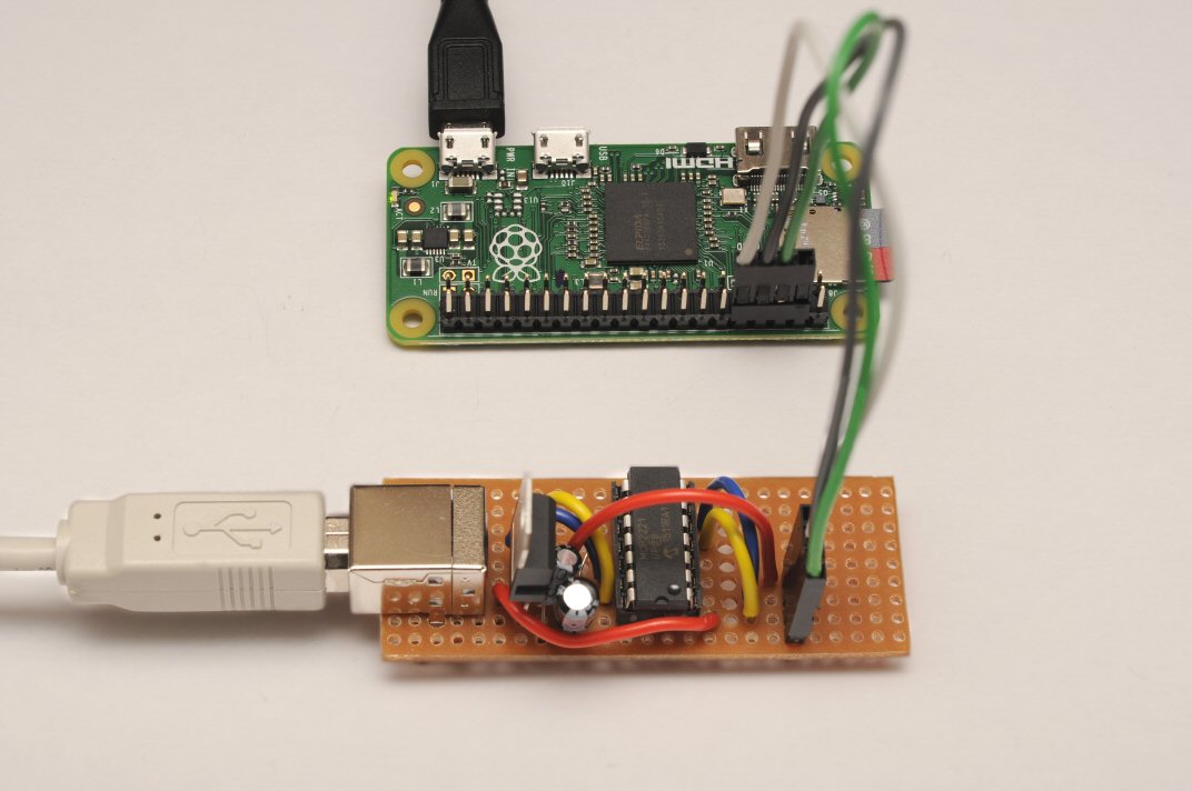
Following this photo of the build I did add some female headers to allow jumping with male pins to a Pi board.
The 5v from USB has been kept as an output pin which allows the board to power a Pi. Reading up on how the Pi manages power, the 5v pin on the header pins bypasses the 700mA ployfuse. This is bad news if something goes wrong over the USB power. For peace-of-mind a polyfuse between 500mA to 700mA can be used to ensure the same protection is available.
A reset switch for the chip could be nice feature if switching between HID modes and UART.
Hooking up
Windows
Starting up with a connection to a Windows PC is good to check everything works as expected because Microchip provide some easy to use software for configuration.
The drivers and utility software can all be downloaded from the Microchip website. Install the driver and the utility. DLLs are not necessary and seem to be library interfaces for building your own code.

Connection between the Pi and the USB UART crosses the receive and transmit lines, which means UTx connects to RXD and URx connects to TXD.
Windows will attempt to locate the driver and install. I'm not entirely sure if these were fetched from Windows update or used the installed driver on my Windows 7 machine. Either way it worked and was successful.

Initial connection throws an Error Encountered message and configuration is only read after pressing the Read Device Settings button.
Settings are written back using the Configure Device button
From the utility window the entire chip can be configured. Serial numbers are not enabled by default so if the device is plugged into another USB a new COM port will be allocated.
The 2221 should be reset after using this utility as the UART and HID modes interrupt each other.


COM3 was allocated first for the device so connecting up was simple using PuTTY.
The 2221 chip sets the transfer speed on first connection. Once set and connected for the first time, altering the serial speed again will create garbage on the screen. Rest the Pi to alter the speed.
Power up the Pi and give time to boot up.
Connect over serial, set the speed and type in the name of the COM device allocated to the USB. Press Open should connect up. Text may appear. Entering the username to login with will tend to get it all going
Linux
Linux requires the CDC driver. Wire up the Pi to the USB/UART board and plug into the Linux machine. Checking dmesg and run
> lsmod | grep cdc
should confirm there's a valid driver and a connection.
With Minicom installed the connection is as easy as
> sudo minicom -b 115200 -o -D /dev/ttyACM0
Power up the Pi and Minicom will show the entire boot sequence. Powering the Pi first seems to set the serial speed.
Using a Pi over serial
Connections over serial remain open all the time regardless of having PuTTY or Minicom open. I found I could kill the terminal process over the serial link with a CTRL-D and the only recourse was to pull the power. Using logout returns the serial console to the login prompt.
Powering down a Pi over serial gives a clean shutdown instead of pulling the plug
> sudo shutdown -h now
A Zero will turn off its LED when shutdown.
Powering the Pi over USB
Essentially this already happens with a micro USB cable connection to a Pi. For the USB/UART device it's a 2 in 1 deal allowing connection and power.
The Windows utility from Microchip allows some tweaking of the power options for USB.
A quick search on the Internet reveals the different current draws for each Pi
- A+ and B+ up to 240mA running idle
- 2 B up to 420mA running idle
- Zero up to 70mA idle and reported to be around 140mA booting up

The bullets above will need adjusting depending on what the Pis are running off USB or header pins.
A Pi 2 will need all the USB power to run so the configuration will need changing to 500mA. I tested booting up a Zero and it worked fine with the 100mA default.
Differences over reference build
This was based on the blog posting from Element 14s community site. Definitely go and visit that post if you plan to do a similar build.
I changed this build and removed the jumper pins knowing that I would only be using these with my Raspberry Pi(s). Without the 5v power to the 2221, the internal LDO isn't used. This also meant one less capacitor on the 2221 VUSB output.
I have read in Simon Monks Raspberry Pi Cookbook that the Arduino can work with 3.3v on the transmit and receive lines. This could mean my 3.3v build works on Arduino, but check out the facts before attempting it as it may not be reliable or good for the Arduino over long term use.
No comments:
Post a Comment