Pimoroni sell the Enviro pHAT, which is a really good little package to go on top of a Raspberry Pi.
I was looking around for a temperature and humidity sensor and this has all of that plus motion, colour and analogue. I'm not sure how all of these can be used together but even separately these components can cost you more in separate breakout boards so not much loss to only use 1 or 2 of these features.
Combined with Scroll pHAT
The Scroll pHAT is great for text. Combined with the Enviro pHat this can show temperature, heading, pressure and motion.
The video shows the motion sensors reaction to being moved in the x and y axis. The dot can be thrown around which is a fun bit of code.
Combined with Unicorn pHat
The Unicorn pHAT is just a colour frenzy. Text can be displayed, but this is fairly limited due to only having 4 LEDs high to play with.
To show the light/colour sensor I sent the values directly to the Unicorn pHat.
Blue
Green
Red
Yellow
The camera doesn't pick the colours up as clearly as they were shown. The colours weren't correct for green and this showed up as a blue colour, but quite fun to play around with.
PaPiRus e-ink screen is an interesting display for the Raspberry Pi. I thought it would be a good idea to start putting the screen to work and try out something I could take out and use.
GPS has saved me when footpaths disappear in the middle of nowhere. A dedicated device to help locate me and also track where I've been seemed like a good project idea. This current instance is fairly basic but the plan is to steal a few ideas from fitness and tracking apps and reuse here.
Specification
Portable, low power, battery supplied, GPS device with the ability to view where I am on the OSGB36 grid and run for at least 3 hours.
In detail:
3 hours running time
Log my journey and provide a view of the data
Start/stop the logging
Provide
Distance
Split time per mile
Where I am on the OSGB36 grid and WGS84
Secondary goals
Min/max altitude
Climb rates split per mile
Visible mapping of journey
What's gone into the build?
A PaPiRus screen has been included to provide a low power display solution. The build uses the full sized PaPiRus and it works fine attached to a Pi Zero.
The Pi Zero was used because, it's cheap, small and should also help keep the power usage low. The Zero's ability to work as a gadget over USB is awesome for a device in a box. Network gadget feature is used so the software can be maintained easily and web services provided.
The cheaper GP-20U7 module has been selected from Proto-Pic for use in this build. The JST connector was cut off and a jumper connector added to work with a custom strip board.
A Sparkfun LiPo charger and power booster has been included to provide power using either 400, 500 or 1000mAh LiPos. The aim is to use the 1000mAh to get the longest life. An evolution of the design included power management and this is handled by a Sparkfun Fuel Gauge.
The luxury items here are the push buttons. These are from Sparkfun and come with illuminated LED rings.
A custom strip board has been used to add in headers to connect up buttons, I2C and the GPS. A couple of NPN transistors are on the board to switch 5v to illuminate the button LEDs.
To provide some connectivity to the outside world a female USB breakout board from Sparkfun has also been used with a stripped down micro USB cable to provide power and data.
All of these components are housed in a 41x77x101 ABS. It's a fairly snug fit for the PaPiRus, Zero and strip board.
After some drilling and cutting, all the components fit in neatly. Liberal use of electrical tape provides some protection from components touching and sending 5/3.3v the wrong way.
Getting it running
By default the PaPiRus display uses the UART pins, but there's a build option for the PaPiRus to exclude these and change the required GPIO pins used by the display. UART pins are used by the GPS module so excluding them was necessary. This was tested before assembly of the components by carefully running jumper pins to the PaPiRus. Unfortunately there was one issue which only revealed itself on assembly which was down to the RXD line. When GPS data is actually going to the RXD the PaPiRus display wouldn't work.
Header surgery on the Pi Zero
The only option at this stage was to snip the GPIO pin going to the display. In hindsight this could have managed this on the strip board layer by designing it to sit between the Zero and the PaPiRus. I wouldn't have been happy to do this to my Pi 2 or 3, but this isn't a concern with the Zero as there are no plans to reuse it on another project.
Controls
The 2 buttons provide basic control. The green button provides a way to change the display and when held it will shutdown the Pi Zero. The white button provides a way to enable the GPS tracking by holding the button and also control what's displayed on the screen with a brief press.
A top switch was fitted later into the build as a way to pull the EN line low on the LiPo booster and charger to reduce the power consumption. This doesn't entirely stop the battery from draining due to a quiescent current and a pull up resistor on the EN line. The switch also disconnects the LiPo Fuel Gauge to prevent any charge being lost through the MAX17043.
View of final assembly
Video
This is a basic demonstration to show the GPS and how the e-ink screen looks presenting the data
Thoughts
My initial wiring of the strip board included a connection to the SCL pin to wake from halt. Whilst this worked to wake up the Raspberry Pi this wasn't a very logical mix with another GPIO input pin and caused false pin state changes and interrupted the SCL when pressed. The connection was removed after implementing the power switch and provided another way to start up after halting.
A micro USB wire was stripped adding female jumper connectors to break out the power and data lines. Since this was a 4 wire USB cable it didn't come with an ID line. A 5 wire cable would allow this to be connected and an OTG connection supported. OTG would allow a WiFi dongle and connection to a hub to support more devices and charging. 4 wire is fine and the network gadget functionality provides charge and connectivity.
The ability to completely turn off power would be useful. Putting the switch in-between the LiPo and charger would allow complete isolation and prevent slow battery drain. The 1000mAh battery seems to drop by 8% a day at the moment, but this hasn't been measured properly.
As part of a larger project I've used the Sparkfun Power Cell and the Sparkfun Fuel Gauge boards to provide power, charging and reporting for a LiPo battery.
This post is about how the components can be configured with a Raspberry Pi and code which can be used to read the Fuel Gauge.
Power Cell
This board is a great size for a project due to the square setup of the components. There's a couple of small changes, which would be good to see and that's having all the pins on one side and also including access to the battery terminals. I had to solder a couple of pins to the underside of the Power Cell to access the battery terminals for the Fuel Gauge. For my current project I don't use the micro USB and instead I wire into the charge pins. This widens the board footprint when using jumper headers.
Adafruit also sell the similar PowerBoost 500 board and this retails at a slightly lower price. I have one of these for another project and it appears to facilitate pins on just one side so it may be a future favorite.
Fuel Gauge
This small board fills an essential gap for any project using a battery. We are all so used to consumer technology telling us how much power we have remaining that, unless you are OK with a project just shutting down without warning, then this is going to be an important feature. I like that this is quite a small and easy to embed into a small gap.
Sparkfun sell an all-in-one board called the Babysitter and although this has all the components in one board it's quite big. I haven't yet seen the Babysitter for sale in the UK so for that reason I also settled for the Fuel Gauge.
For my use the JST connector was a bit useless and it would be nice to have just a breakout board for the MAX17043. Architecturally it's feasible to connect a battery to this board first and wire up jumpers connected to another female JST to go into the charging board. I've not tried it this way and can't guarantee that this would work, but could be tidier in some solutions.
Be aware that the VCC and GND pins provide output. I mistakenly thought these were to power the logic but that comes direct from the battery. Luckily I got away with this and didn't fry my Pi although I was surprised to see my Zero attempting to boot up when powered from the 3V rail.
Wiring Up
I've tried to show this in Fritzing as I don't have a neat breadboard setup to provide a visual. In my setup I have an independent female micro USB for power and data. The Pi Zero can be powered from the data USB which I take advantage of. The micro USB connection shown here is actually a 4 wire, male USB cable with female jumper cable connectors. 5 wire is necessary to have OTG functionality over USB.
If you just want to power your Pi then you can remove the USB connectors and plug straight into the Power Cell. The 5V and GND outputs can go directly to the GPIO pins 4 & 6.
A switch has been included to pull the EN pin low to stop power going to the Pi Zero. I also use it to cut the ground pin to the Fuel Gauge.
The Fuel Gauge is shown as a MAX1704X board since there isn't a part in Fritzing. SDA and SCL are connected up to allow I2C communication. GND needs to go to a GND on the Pi to allow the logic to work on the Fuel Gauge. I haven't used the alerting output in my project as I'm not sure when I would need a hardware interrupt instead of my own software control.
Finally you can include any LiPo battery as long as it meets the specification of the Sparkfun Power Cell and Fuel Gauge. I've shown a 110mAh as it was a small example for this diagram, but practically that will be too small for most projects that need a few hours of operation.
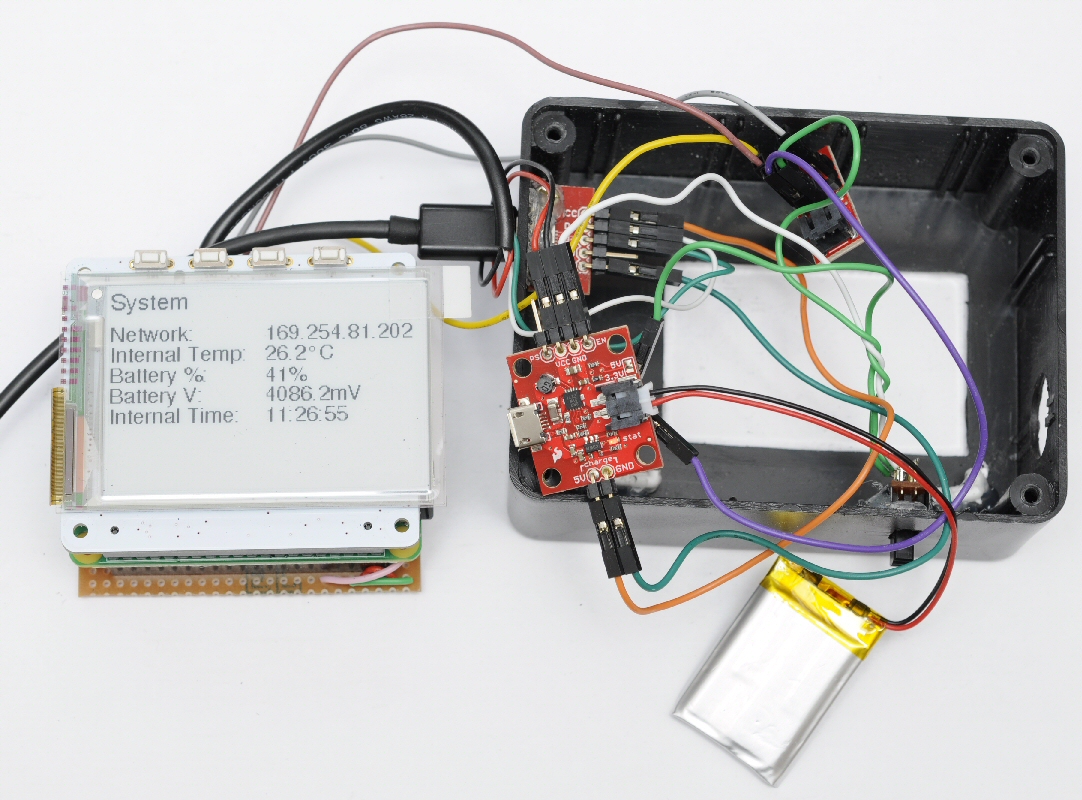
I've added a picture of the (messy) implementation. I have a Sparkfun female USB breakout glued to the edge of the box. The Zero is hidden under the PaPiRus display. A power switch has been glued in to the box and pulls the EN low as shown in the diagram above.
Note that even though the output can be switched off the Power Cell still draws a small amount of current from the battery. If left for a few days then most small batteries will completely drain. I've not confirmed how long this really takes but a few % of power has been noted to drop from a 1000mAh battery when left off overnight.
Code for Fuel Cell
I've included a really simple example used to query the bus and read the percentage remaining and voltage. Verify the Fuel Gauge address on the bus with i2cdetect. I've found that it runs on 0x36 (0x6C MSB) and as far as I'm aware this isn't configurable.
The percentage is very simple to read. So simple I didn't need to wrap in a function.
The voltage is a little more involved with the byte swapping. Practically I'm not sure why the voltage would be useful in an application. It may be significant if the battery is under load and could provide some early warnings in an application. Fully charged LiPo batteries read over 3.7V so don't worry if the value seems high as the output should be regulated by the Power Cell.
Other Info
You can find some information about batteries on the Sparkfun learn site at learn.sparkfun.com/tutorials/battery-technologies. There's a LiPo voltage curve which shows the high initial voltage and what can be expected over time.
Adafruit PowerBoost 500 + Charger
As mentioned earlier Adafruit have an alternative LiPo 5V booster and charger, which is a good alternative to the Sparkfun board. This is a picture of one that I've bought for future use.
Breakout pins are all along the top so it's easier to plan connections in a small enclosure. I expect that this suffers from a similar amount of battery drain when EN is pulled low.
There are more LED indicators on this board than the Sparkfun and these show low battery (red), 5v active (blue), charging (yellow) and fully charged (green). This is great for an open project, but you will need a transparent case to make the most of this for any enclosed project.