Power Cell and Fuel Cell Integration
As part of a larger project I've used the Sparkfun Power Cell and the Sparkfun Fuel Gauge boards to provide power, charging and reporting for a LiPo battery.
This post is about how the components can be configured with a Raspberry Pi and code which can be used to read the Fuel Gauge.
Power Cell

Adafruit also sell the similar PowerBoost 500 board and this retails at a slightly lower price. I have one of these for another project and it appears to facilitate pins on just one side so it may be a future favorite.
Fuel Gauge

Sparkfun sell an all-in-one board called the Babysitter and although this has all the components in one board it's quite big. I haven't yet seen the Babysitter for sale in the UK so for that reason I also settled for the Fuel Gauge.
For my use the JST connector was a bit useless and it would be nice to have just a breakout board for the MAX17043. Architecturally it's feasible to connect a battery to this board first and wire up jumpers connected to another female JST to go into the charging board. I've not tried it this way and can't guarantee that this would work, but could be tidier in some solutions.
Be aware that the VCC and GND pins provide output. I mistakenly thought these were to power the logic but that comes direct from the battery. Luckily I got away with this and didn't fry my Pi although I was surprised to see my Zero attempting to boot up when powered from the 3V rail.
Wiring Up

I've tried to show this in Fritzing as I don't have a neat breadboard setup to provide a visual. In my setup I have an independent female micro USB for power and data. The Pi Zero can be powered from the data USB which I take advantage of. The micro USB connection shown here is actually a 4 wire, male USB cable with female jumper cable connectors. 5 wire is necessary to have OTG functionality over USB.
If you just want to power your Pi then you can remove the USB connectors and plug straight into the Power Cell. The 5V and GND outputs can go directly to the GPIO pins 4 & 6.
A switch has been included to pull the EN pin low to stop power going to the Pi Zero. I also use it to cut the ground pin to the Fuel Gauge.
The Fuel Gauge is shown as a MAX1704X board since there isn't a part in Fritzing. SDA and SCL are connected up to allow I2C communication. GND needs to go to a GND on the Pi to allow the logic to work on the Fuel Gauge. I haven't used the alerting output in my project as I'm not sure when I would need a hardware interrupt instead of my own software control.
Finally you can include any LiPo battery as long as it meets the specification of the Sparkfun Power Cell and Fuel Gauge. I've shown a 110mAh as it was a small example for this diagram, but practically that will be too small for most projects that need a few hours of operation.
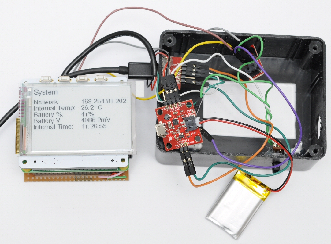
I've added a picture of the (messy) implementation. I have a Sparkfun female USB breakout glued to the edge of the box. The Zero is hidden under the PaPiRus display. A power switch has been glued in to the box and pulls the EN low as shown in the diagram above.
Note that even though the output can be switched off the Power Cell still draws a small amount of current from the battery. If left for a few days then most small batteries will completely drain. I've not confirmed how long this really takes but a few % of power has been noted to drop from a 1000mAh battery when left off overnight.
Code for Fuel Cell
I've included a really simple example used to query the bus and read the percentage remaining and voltage. Verify the Fuel Gauge address on the bus with i2cdetect. I've found that it runs on 0x36 (0x6C MSB) and as far as I'm aware this isn't configurable.
import smbus
import time

BATT_SENSOR_ADDRESS = 0x36

def get_batt_voltage(bus):
 high_val = 0
 low_val = 0
  high_val = bus.read_byte_data(BATT_SENSOR_ADDRESS,0x02)
  low_val = bus.read_byte_data(BATT_SENSOR_ADDRESS,0x03)
 raw_val = ((low_val | (high_val << 8)) >> 4)
 return raw_val * 1.25

bus = smbus.SMBus(1)

while True:
 battery_remaining = bus.read_byte_data(BATT_SENSOR_ADDRESS,0x04)
 battery_voltage = get_batt_voltage(bus)

 print("Battery % = {0}, V = {1}mV".format(battery_remaining, battery_voltage))

 time.sleep(5)
The voltage is a little more involved with the byte swapping. Practically I'm not sure why the voltage would be useful in an application. It may be significant if the battery is under load and could provide some early warnings in an application. Fully charged LiPo batteries read over 3.7V so don't worry if the value seems high as the output should be regulated by the Power Cell.
Other Info
You can find some information about batteries on the Sparkfun learn site at learn.sparkfun.com/tutorials/battery-technologies. There's a LiPo voltage curve which shows the high initial voltage and what can be expected over time.
Adafruit PowerBoost 500 + Charger

As mentioned earlier Adafruit have an alternative LiPo 5V booster and charger, which is a good alternative to the Sparkfun board. This is a picture of one that I've bought for future use.
Breakout pins are all along the top so it's easier to plan connections in a small enclosure. I expect that this suffers from a similar amount of battery drain when EN is pulled low.
There are more LED indicators on this board than the Sparkfun and these show low battery (red), 5v active (blue), charging (yellow) and fully charged (green). This is great for an open project, but you will need a transparent case to make the most of this for any enclosed project.
There's a good overview on the Adafruit site at learn.adafruit.com/adafruit-powerboost-500-plus-charger/overview.
No comments:
Post a Comment